Vacuum check valve. Vacuum reservoir
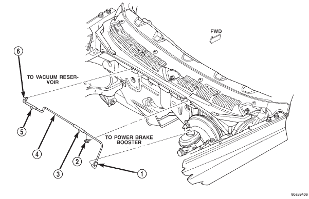
(1) Unplug the vacuum supply line connector at
the vacuum check valve (Fig. 88).
(2) Note the orientation of the check valve in the
vacuum supply line for correct reinstallation.
(3) Unplug the vacuum check valve from the vacuum
supply line fittings.
(4) Reverse the removal procedures to install. (1) Disconnect and isolate the battery negative
cable.
(2) Remove the wiper arms from the wiper pivots.
Refer to Wiper Arm in the Removal and Installation
section of Group 8K - Wiper and Washer Systems for
the procedures.
1 - VACUUM CHECK VALVE 2 - CLIP 3 - TO HEATER-AC CONTROLS 4 - VACUUM SUPPLY LINE 5 - TO SPEED CONTROL SERVO 6 - GROMMET (3) Remove the weatherstrip along the front edge
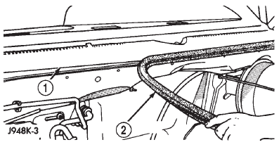
of the cowl plenum cover/grille panel and the cowl
plenum panel (Fig. 89).
1 - COWL GRILLE 2 - WEATHERSTRIP (4) Remove the four plastic nuts that secure the
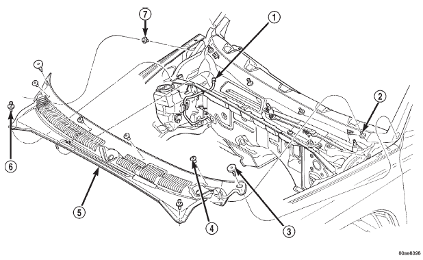
cowl plenum cover/grille panel to the studs on the
cowl top panel near the base of the windshield (Fig.
90).
(5) Remove the one plastic rivet that secures the
front corner on each side of the cowl plenum cover/
grille panel to the cowl plenum panel.
(6) Remove the one plastic push-in retainer that
secures the rear corner on each side of the cowl plenum
cover/grille panel to the windshield reveal molding.
(7) Unsnap the slotted center hole on each side of
the cowl plenum cover/grille panel from the adhesivebacked
snap fastener. (If equipped: This feature
may not be on all models).
(8) Lift the cowl plenum cover/grille panel from the
cowl top far enough to access the windshield washer
nozzle and vacuum plumbing near the right end of
the cowl plenum.
(9) Disconnect the windshield washer supply hose
at the in-line connector.
(10) Disconnect the vacuum supply hose from the
vacuum reservoir, which is secured to the underside
of the right end of the cowl plenum cover/grille panel
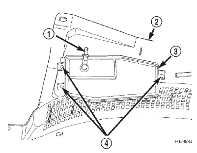
(Fig. 91).
1 - IN-LINE WASHER SUPPLY HOSE CONNECTOR 2 - STUD 3 - PUSH-IN PLASTIC RETAINER 4 - PLASTIC NUT 5 - COWL PLENUM COVER/GRILLE PANEL 6 - PLASTIC RIVET 7 - ADHESIVE-BACKED SNAP FASTENER
1 - VACUUM SUPPLY CONNECTOR 2 - COWL PLENUM COVER/GRILLE PANEL 3 - VACUUM RESERVOIR 4 - SCREWS (11) Remove the cowl plenum cover/grille panel
from the vehicle.
(12) Remove the three screws that secure the vacuum
reservoir to the underside of the cowl plenum
cover/grille panel.
(13) Remove the vacuum reservoir from the cowl
plenum cover/grille panel.
(14) Reverse the removal procedures to install.
Tighten the vacuum reservoir mounting screws to 2.2
N*m (20 in. lbs.).Vacuum check valve
Vacuum reservoir
 Fig. 88 Vacuum Supply
 Fig. 89 Cowl Plenum Cover/Grille Panel Weatherstrip
 Fig. 90 Cowl Plenum Cover/Grille Panel Remove/Install
 Fig. 91 Vacuum Reservoir
Dodge Durango (DN) 1998-2003 Service Manual
- Lubrication and Maintenance
- Suspension
- Differential and Driveline
- Brakes
- Cooling System
- Battery
- Starting Systems
- Charging System
- Ignition System
- Instrument Panel Systems
- Audio Systems
- Horn Systems
- Speed Control System
- Turn Signal and Hazard Warning Systems
- Wiper and Washer Systems
- Lamps
- Passive Restraint Systems
- Electrically Heated Systems
- Power Distribution System
- Power Lock Systems
- Vehicle Theft/Security Systems
- Power Seat System
- Power Window Systems
- Power Mirror Systems
- Chime/Buzzer Warning Systems
- Overhead Console Systems
- Engine
- Exhaust System
- Frame and Bumpers
- Fuel System
- Steering
- Transmission and Transfer Case
- Tires and Wheels
- Body
- Heating and Air Conditioning
- Emission Control Systems
- Introduction
