Removal and installation
The PCV valve is located on the oil filler tube (Fig.
20). Two locating tabs are located on the side of the
valve (Fig. 20). These 2 tabs fit into a cam lock in the
oil filler tube. An o-ring seals the valve to the filler
tube. REMOVAL (1) Disconnect PCV line/hose (Fig. 20) by disconnecting
rubber hose at PCV valve fitting.
(2) Remove PCV valve at oil filler tube by rotating
PCV valve downward (counter-clockwise) until locating
tabs have been freed at cam lock (Fig. 20). After
tabs have cleared, pull valve straight out from filler
tube. To prevent damage to PCV valve locating
tabs, valve must be pointed downward for
removal. Do not force valve from oil filler tube.
(3) After valve is removed, check condition of valve
o-ring (Fig. 20).
1 - O-RING 2 - LOCATING TABS 3 - CAM LOCK 4 - OIL FILLER TUBE 5 - PCV LINE/HOSE 6 - PCV VALVE INSTALLATION (1) Return PCV valve back to oil filler tube by
placing valve locating tabs (Fig. 20) into cam lock.
Press PCV valve in and rotate valve upward. A slight
click will be felt when tabs have engaged cam lock.
Valve should be pointed towards rear of vehicle.
(2) Connect PCV line/hose and rubber hose to PCV
valve The EVAP canister is located below the vehicle,
inside the left frame rail, in front of the fuel tank
(Fig. 21). REMOVAL (1) Raise vehicle.
(2) Disconnect vacuum lines at EVAP canister.
Note location of lines before removal.
(3) Remove canister mounting nut.
1 - LEFT FRAME RAIL 2 - RUBBER GROMMETS (2) 3 - LOCATING PINS (2) 4 - EVAP CANISTER 5 - MOUNTING NUT 6 - MOUNTING BRACKET (4) Remove canister from mounting bracket. INSTALLATION (1) Position canister locating pins into mounting
bracket grommets (Fig. 21) and install mounting nut.
(2) Tighten mounting nut to 17-24 N*m (150-210
in. lbs.) torque.
(3) Connect vacuum lines at canister.
(4) Lower vehicle The duty cycle EVAP canister purge solenoid is
located at the left-rear side of engine compartment
near power brake vacuum unit (Fig. 22). REMOVAL (1) Disconnect electrical wiring connector at solenoid
(2) Disconnect vacuum harness at solenoid.
(3) Remove 2 support bracket mounting nuts.
(4) Remove solenoid and its support bracket from
vehicle. INSTALLATION (1) Position EVAP canister purge solenoid and its
mounting bracket.
(2) Install mounting nuts and tighten to 8 N*m (75
in. lbs.) torque.
(3) Connect vacuum harness and wiring connector.
1 - BRACKET NUTS (2) 2 - EVAP CANISTER PURGE SOLENOID 3 - EVAP SYSTEM TEST PORT (IF EQUIPPED) 4 - VACUUM LINES 5 - ELECTRICAL CONNECTOR Two rollover valves are used. One of the valves is
permanently mounted to top/rear of fuel tank (Fig.
23). If replacement of this particular valve is necessary,
the fuel tank must be replaced. Refer to Fuel
Tank Removal/Installation in Group 14, Fuel System.
The other rollover valve is located on top of the fuel
pump module (Fig. 23). This valve may be serviced
separately. Refer to following steps for procedures.
1 - FUEL PUMP MODULE 2 - FRONT ROLLOVER VALVE 3 - FUEL FILTER/FUEL PRESSURE REGULATOR 4 - FUEL TANK 5 - EVAP LINE 6 - REAR ROLLOVER VALVE REMOVAL WARNING: THE FUEL SYSTEM IS UNDER A CONSTANT
PRESSURE (EVEN WITH THE ENGINE OFF).
BEFORE SERVICING THE ROLLOVER VALVE(S),
FUEL SYSTEM PRESSURE MUST BE RELEASED.
REFER TO FUEL PRESSURE RELEASE PROCEDURE
IN GROUP 14, FUEL SYSTEM. (1) Disconnect negative battery cable at battery.
(2) Remove fuel filler cap and drain fuel tank.
(3) Remove fuel tank. Refer to Fuel Tank Removal/
Installation in Group 14, Fuel System.
(4) Disconnect tube (line) at valve.
(5) The rollover valve is seated into a rubber grommet.
Remove valve by prying one side upward and
then roll valve out of grommet.
(6) Discard old grommet. INSTALLATION (1) Install new grommet into fuel pump module.
(2) Using finger pressure only, press valve into
place.
(3) Install fuel tank. Refer to Fuel Tank Installation.
(4) Fill fuel tank. Install fuel tank filler cap.
(5) Connect negative battery cable.
(6) Start vehicle and check for leaks. The LDP is located in the engine compartment
under the battery tray and Power Distribution Center
(PDC) (Fig. 24). The LDP filter is attached to the
outside of battery tray (Fig. 25). The LDP and LDP
filter are replaced (serviced) as one unit. REMOVAL (1) Disconnect negative battery cable at battery.
(2) Remove battery. Refer to Group 8A, Battery for
procedures.
(3) Carefully disconnect rubber hose from bottom
of LDP filter (Fig. 25).
(4) Remove clip retaining LDP filter to battery
tray (Fig. 25) and remove filter from tray.
(5) Disconnect battery temperature sensor pigtail
wiring harness at bottom of battery tray.
(6) To gain access to LDP, the PDC must be partially
removed. Remove PDC-to-fender mounting
screw at rear of PDC. Unsnap PDC from battery
tray. To prevent damage to PDC wiring, carefully
position PDC to gain access to LDP.
(7) Remove battery tray. Refer to Group 8A, Battery
for procedures.
(8) Carefully remove vapor/vacuum lines at LDP.
(9) Disconnect electrical connector at LDP.
1 - BATTERY 2 - LEAK DETECTION PUMP
(LDP)
1 - LDP FILTER 2 - LDP FILTER-TO-LDP HOSE 3 - BATTERY TRAY 4 - LDP MOUNTING CLIP (10) Remove 3 LDP mounting screws (Fig. 26) and
remove LDP from vehicle. INSTALLATION (1) Install LDP to bottom of battery tray. Tighten
screws to 1 N*m (11 in. lbs.) torque.
(2) Carefully install vapor/vacuum lines to LDP.
1 - BATTERY TRAY 2 - LDP 3 - LDP MOUNTING SCREWS (3) The vapor/vacuum lines and hoses must be
firmly connected. Check the vapor/vacuum
lines at the LDP, LDP filter and EVAP canister
purge solenoid for damage or leaks. If a leak is
present, a Diagnostic Trouble Code (DTC) may
be set.
(3) Connect electrical connector to LDP.
(4) Install battery tray. Refer to Group 8A, Battery
for procedures.
(5) Install PDC to fender and battery tray (snaps
on to battery tray).
(6) Install LDP filter to battery tray (one clip).
(7) Install connecting hose to bottom of LDP filter.
(8) Connect battery temperature sensor pigtail
wiring harness.
(9) Install battery. Refer to Group 8A, Battery for
procedures.
(10) Connect negative battery cable to battery. Specifications TORQUE CHART Description - Torque EVAP Canister Mounting Nut . . . . . . . . 17-24 N*m
(150-210 in. lbs.) EVAP Canister Purge Solenoid Mounting
Bolt . . . . . . . . . . . . . . . . . . . . 11 N*m (95 in. lbs.) Leak Detection Pump (LDP) Mounting
Screws . . . . . . . . . . . . . . . . . . 1 N*m (11 in. lbs.)Pcv valve-4.7L v-8 engine
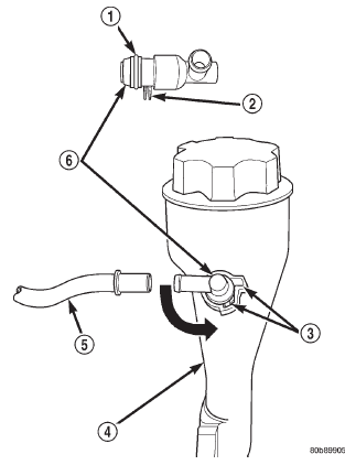 Fig. 20 PCV Valve/Oil Filler Tube Location
Evaporation (evap) canister
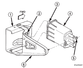 Fig. 21 EVAP Canister Location
Duty cycle evap canister purge solenoid
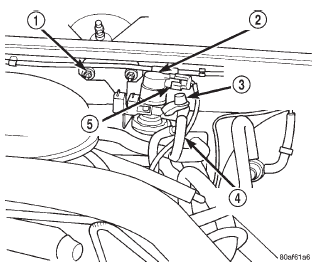 Fig. 22 Duty Cycle EVAP Canister Purge Solenoid
Rollover valve(s)
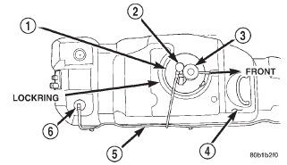 Fig. 23 Rollover Valve Locations
Leak detection pump (ldp)
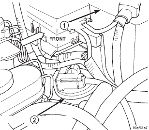 Fig. 24 Leak Detection Pump (LDP) Location
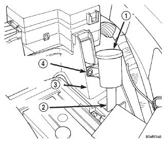 Fig. 25 LDP Filter Location
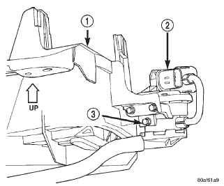 Fig. 26 Leak Detection Pump (LDP) Mounting Screws
Dodge Durango (DN) 1998-2003 Service Manual
- Lubrication and Maintenance
- Suspension
- Differential and Driveline
- Brakes
- Cooling System
- Battery
- Starting Systems
- Charging System
- Ignition System
- Instrument Panel Systems
- Audio Systems
- Horn Systems
- Speed Control System
- Turn Signal and Hazard Warning Systems
- Wiper and Washer Systems
- Lamps
- Passive Restraint Systems
- Electrically Heated Systems
- Power Distribution System
- Power Lock Systems
- Vehicle Theft/Security Systems
- Power Seat System
- Power Window Systems
- Power Mirror Systems
- Chime/Buzzer Warning Systems
- Overhead Console Systems
- Engine
- Exhaust System
- Frame and Bumpers
- Fuel System
- Steering
- Transmission and Transfer Case
- Tires and Wheels
- Body
- Heating and Air Conditioning
- Emission Control Systems
- Introduction
Categories
