Gearshift cable. Band adjustments
Check adjustment by starting the engine in Park
and Neutral. Adjustment is OK if the engine starts
only in these positions. Adjustment is incorrect if the
engine starts in one but not both positions. If the
engine starts in any position other than Park or Neutral,
or if the engine will not start at all, the park/
neutral position switch may be faulty. Gearshift Adjustment Procedure 1) Shift transmission into Park.
(2) Release cable adjuster lock (underneath the
power brake booster) (Fig. 308) to unlock cable.
(3) Raise vehicle.
(4) Slide cable eyelet off transmission shift lever.
(5) Verify transmission shift lever is in Park
detent by moving lever fully rearward. Last rearward
detent is Park position.
(6) Verify positive engagement of transmission
park lock by attempting to rotate propeller shaft.
Shaft will not rotate when park lock is engaged.
(7) Slide cable eyelet onto transmission shift lever.
(8) Lower vehicle and check engine starting.
Engine should start only in Park and Neutral.
(9) Lock shift cable by pressing cable adjuster
clamp down until it snaps into place. FRONT BAND ADJUSTMENT The front (kickdown) band adjusting screw is
located on the left side of the transmission case
above the manual valve and throttle valve levers.
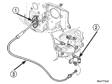
1 - CABLE MOUNTING 2 - CABLE BRACKET AT TRANS. 3 - GEARSHIFT CABLE (1) Raise vehicle.
(2) Loosen band adjusting screw locknut (Fig. 309).
Then back locknut off 3-5 turns. Be sure adjusting
screw turns freely in case. Apply lubricant to screw
threads if necessary.
(3) Tighten band adjusting screw to 8 N*m (72 in.
lbs.) torque with Inch Pound Torque Wrench
C-3380-A, a 3-in. extension and appropriate Torxy
socket. CAUTION: If Adapter C-3705 is needed to reach the
adjusting screw, tighten the screw to only 5 N*m
(47-50 in. lbs.) torque. 42RE TRANSMISSION 44RE TRANSMISSION (4) Lower vehicle. REAR BAND ADJUSTMENT The transmission oil pan must be removed for
access to the rear band adjusting screw.
(1) Raise vehicle.
(2) Remove transmission oil pan and drain fluid.
(3) Loosen band adjusting screw locknut 5-6 turns
(Fig. 310). Be sure adjusting screw turns freely in
lever.
(4) Tighten adjusting screw to 8 N*m (72 in. lbs.)
torque.
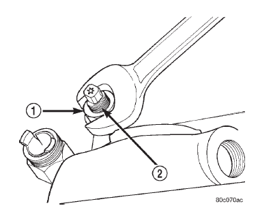
1 - LOCK-NUT 2 - FRONT BAND ADJUSTER
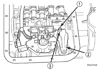
1 - ADJUSTING SCREW 2 - REAR BAND LEVER 3 - LOCKNUT 42/44RE TRANSMISSION 5) Position new gasket on oil pan and install pan
on transmission. Tighten pan bolts to 17 N*m (13 ft.
lbs.) torque.
(6) Lower vehicle and refill transmission with
Mopart ATF Plus 3, Type 7176 fluid.Gearshift cable
Band adjustments
 Fig. 308 Gearshift Cable Routing
 Fig. 309 Front Band Adjustment Screw Location
 Fig. 310 Rear Band Adjusting Screw Location
Dodge Durango (DN) 1998-2003 Service Manual
- Lubrication and Maintenance
- Suspension
- Differential and Driveline
- Brakes
- Cooling System
- Battery
- Starting Systems
- Charging System
- Ignition System
- Instrument Panel Systems
- Audio Systems
- Horn Systems
- Speed Control System
- Turn Signal and Hazard Warning Systems
- Wiper and Washer Systems
- Lamps
- Passive Restraint Systems
- Electrically Heated Systems
- Power Distribution System
- Power Lock Systems
- Vehicle Theft/Security Systems
- Power Seat System
- Power Window Systems
- Power Mirror Systems
- Chime/Buzzer Warning Systems
- Overhead Console Systems
- Engine
- Exhaust System
- Frame and Bumpers
- Fuel System
- Steering
- Transmission and Transfer Case
- Tires and Wheels
- Body
- Heating and Air Conditioning
- Emission Control Systems
- Introduction
