Description and operation. Diagnosis and testing
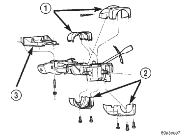
Steering column The tilt and standard column (fig. 1) Has been
designed to be serviced as an assembly; less wiring,
switches, shrouds, steering wheel, etc. Most steering
column components can be serviced without removing
the steering column from the vehicle.
1 - UPPER SHROUD 2 - LOWER SHROUD 3 - PANEL BRACKET SERVICE PRECAUTIONS Safety goggles should be worn at all times when
working on steering columns.
To service the steering wheel, switches or airbag,
refer to Group 8M and follow all WARNINGS and
CAUTIONS. WARNING: THE AIRBAG SYSTEM IS A SENSITIVE,
COMPLEX ELECTRO-MECHANICAL UNIT. BEFORE
ATTEMPTING TO DIAGNOSE, REMOVE OR INSTALL
THE AIRBAG SYSTEM COMPONENTS YOU MUST
FIRST DISCONNECT AND ISOLATE THE BATTERY
NEGATIVE (GROUND) CABLE. THEN WAIT TWO
MINUTES FOR THE SYSTEM CAPACITOR TO DISCHARGE.
FAILURE TO DO SO COULD RESULT IN
ACCIDENTAL DEPLOYMENT OF THE AIRBAG AND
POSSIBLE PERSONAL INJURY. THE FASTENERS,
SCREWS, AND BOLTS, ORIGINALLY USED FOR
THE AIRBAG COMPONENTS, HAVE SPECIAL COATINGS
AND ARE SPECIFICALLY DESIGNED FOR THE
AIRBAG SYSTEM. THEY MUST NEVER BE
REPLACED WITH ANY SUBSTITUTES. ANYTIME A
NEW FASTENER IS NEEDED, REPLACE WITH THE
CORRECT FASTENERS PROVIDED IN THE SERVICE
PACKAGE OR FASTENERS LISTED IN THE PARTS
BOOKS. CAUTION: Do not hammer on steering column
shaft or shift tube. This may cause damage to the
shaft, shift tube or bearing.
CAUTION: Do not attempt to remove or modify the
park lock slider or link.
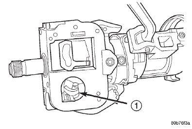
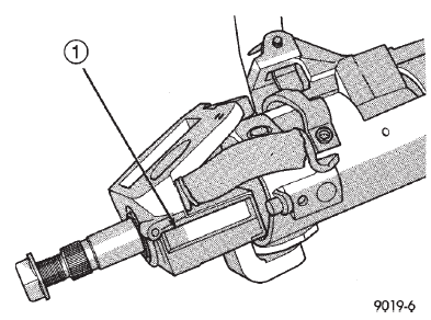
CAUTION: Do not attempt to remove the pivot pins
to disassemble the tilting mechanism. Do not
remove shaft lock plate or plate retainer. This will
damage the column (Fig. 2) and (Fig. 3). Ignition switch TEST AND REPAIR If the key removal effort is excessive on a vehicle
with a automatic transmission first adjust the shift
linkage, refer to Group 21 Transmission And Transfer
Case for procedure.
If the ignition switch effort is excessive remove the
ignition key cylinder from the steering column. Refer to Group 8D Ignition
System. Check the turning
effort of the key cylinder. If the ignition key cylinder
effort is excessive replace the key cylinder. If the
ignition key cylinder operates properly look for the
following conditions.
(1) Look for rough areas or flash in the casting
and if found remove with a file (Fig. 4).
(2) Grease the lock plate actuator, lock plate, slider
and locking link.
1 - CAUTION: NEVER REMOVE SHAFT LOCK PLATE
1 - CAUTION: NEVER REMOVE SHAFT LOCK PLATE RETAINERDescription and operation
 Fig. 1 Steering column
Diagnosis and testing
 Fig. 2 Observe Cautions
 Fig. 3 Observe Cautions
Dodge Durango (DN) 1998-2003 Service Manual
- Lubrication and Maintenance
- Suspension
- Differential and Driveline
- Brakes
- Cooling System
- Battery
- Starting Systems
- Charging System
- Ignition System
- Instrument Panel Systems
- Audio Systems
- Horn Systems
- Speed Control System
- Turn Signal and Hazard Warning Systems
- Wiper and Washer Systems
- Lamps
- Passive Restraint Systems
- Electrically Heated Systems
- Power Distribution System
- Power Lock Systems
- Vehicle Theft/Security Systems
- Power Seat System
- Power Window Systems
- Power Mirror Systems
- Chime/Buzzer Warning Systems
- Overhead Console Systems
- Engine
- Exhaust System
- Frame and Bumpers
- Fuel System
- Steering
- Transmission and Transfer Case
- Tires and Wheels
- Body
- Heating and Air Conditioning
- Emission Control Systems
- Introduction
