Removal and installation
WARNING: BEFORE SERVICING THE STEERING
COLUMN THE AIRBAG SYSTEM MUST BE DISARMED,
REFER TO GROUP 8M RESTRAINT SYSTEMS
FOR SERVICE PROCEDURES. FAILURE TO
DO SO MAY RESULT IN ACCIDENTAL DEPLOYMENT
OF THE AIRBAG AND POSSIBLE PERSONAL
INJURY.
1 - FILE THIS AREA TO REMOVE FLASHING AND PROVIDE
CLEARANCE TO ELIMINATE BINDING 2 - PARK LOCK SLIDER 3 - CAUTION: NEVER REMOVE SHAFT LOCK PLATE CAUTION: All fasteners must be torqued to specification
to ensure proper operation of the steering
column. REMOVAL (1) Position front wheels straight ahead.
(2) Remove the negative (ground) cable from the
battery.
(3) Remove the airbag, refer to Group 8M
Restraint Systems.
(4) Remove the steering wheel with an appropriate
puller. CAUTION: Ensure the puller bolts are fully engaged
into the steering wheel and not into the clockspring,
before attempting to remove the wheel. Failure
to do so may damage the steering wheel/
clockspring. (5) Remove the steering column opening cover and
knee blocker, refer to Group 8E Instrument Panel
Systems.
(6) Disconnect shift cable (column shift vehicles).
Pry shift cable from the shift lever and remove from
cable bracket (Fig. 5).
(7) Remove PRNDL cable (column shift vehicles).
Put shift lever in Park position. Pull cable and twist
to remove from PRNDL lever. Push tab on top of
cable retainer, then squeeze sides to remove retainer
from the column (Fig. 6).
(8) Remove tilt lever (if equipped) from column.
(9) Remove the lower and upper shrouds (Fig. 7).
1 - SHIFT LEVER 2 - STEERING COLUMN 3 - SHIFT CABLE
1 - PRNDL LEVER 2 - THUMB SCREW 3 - CABLE RETAINER 4 - PRNDL CABLE (10) Remove the turn signal multi-function switch
connector with a 7 mm socket (Fig. 8).
(11) Remove remaining electrical connections from
the column switches (Fig. 8).
(12) Remove the bolt and nut from upper intermediate
shaft (Fig. 9). Slide upper intermediate shaft off
column shaft.
(13) Remove column mounting nuts (Fig. 10).
(14) Remove column from vehicle.
(15) Remove clockspring, switches and key cylinder,
refer to Group 8 Electrical for procedures. CAUTION: Failure to follow Group 8 Electrical procedure
for clockspring removal, may damage the
clockspring plastic latches.
1 - UPPER SHROUD 2 - LOWER SHROUD 3 - PANEL BRACKET
1 - MULTI-FUNCTION SWITCH 2 - SPEED CONTROL 3 - IGNITION SWITCH INSTALLATION (1) Install switches, clockspring and key cylinder,
refer to Group 8 Electrical for procedures.
(2) Position the column to the panel bracket and
attaching studs. Install, but loose assemble the
mounting nuts.
(3) Slide upper intermediate shaft onto the column
shaft. Install a new bolt and nut and tighten to 49
N*m (36 ft. lbs.).
(4) Tighten column mounting nuts to 12 N*m (105
in. lbs.).
1 - COUPLER 2 - LOWER SHAFT 3 - TOE PLATE 4 - STEERING COLUMN 5 - UPPER SHAFT 6 - RACK AND PINION STEERING GEAR
1 - MOUNTING NUTS (5) Connect the multi-function switch wiring and
tighten with 7mm socket to 2 N*m (17 in. lbs.).
(6) Install the wiring connections to the column
switches. (7) Install the lower and upper shrouds.
(8) Install the PRNDL cable (column shift vehicles).
Place shifter in Park position. If indicator needs
adjusting turn thumb screw on cable retainer to
adjust cable.
(9) Install shift cable (column shift vehicles).
(10) Install the tilt lever (if equipped).
(11) Install the knee blocker and steering column
opening cover, refer to Group 8E Instrument Panel
Systems for procedures.
(12) Install steering wheel and tighten nut to 47
N*m (35 ft. lbs.).
(13) Install airbag, refer to Group 8M Restraint
Systems for procedure.
(14) Connect the battery ground (negative) cable.
(15) Check operation of the automatic transmission
shift linkage and adjust as necessary. Refer to
Group 21, Transmission and Transfer Case for
adjustment procedure. REMOVAL (1) Support the steering column assembly as
shown in (Fig. 11) using a suitable size socket and
back-up support.
(2) Disconnect over drive switch wiring.
(3) Using a drift of the appropriate size drive the
knurled pin out of the steering column and gear shift
lever. Remove the gear shift lever from the steering
column assembly. CAUTION: The pin can only be removed from the
direction shown (Fig. 11). INSTALLATION (1) Support the steering column using a suitable
size socket and back-up support.
(2) Install the gear shift lever into the steering column
assembly. Align the pin holes in the gear shift
lever and the steering column assembly. CAUTION: The pin must be installed in the original
direction. (3) Carefully Install the pin into the steering column
assembly and through the shift lever. If the pin
binds check the alignment on the holes. Be sure pin
is fully installed into the steering column assembly.
(4) Connect over drive switch wiring.
1 - IGNITION SWITCH 2 - KNURLED PIN 3 - GEARSHIFT LEVER 4 - SOCKET 5 - DRIFT 6 - HAMMER Specifications Torque chart DESCRIPTION TORQUE Steering Column Steering Wheel Nut . . . . . . . . 47 N*m (35 ft. lbs.) Column Bracket Nuts . . . . . 12 N*m (105 in. lbs.) Shaft Coupler Bolts . . . . . . . . 49 N*m (36 ft. lbs.) Multi-function Switch Bolt . . . 2 N*m (17 in. lbs.)Steering column
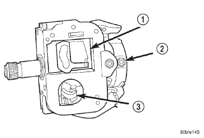 Fig. 4 Steering Column Flash Removal
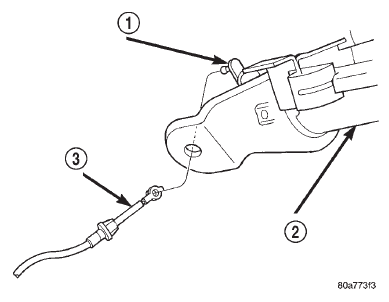 Fig. 5 Shift Cable
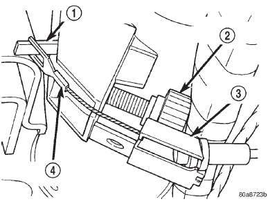 Fig. 6 PRNDL Drive Cable
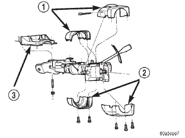 Fig. 7 Column Shrouds
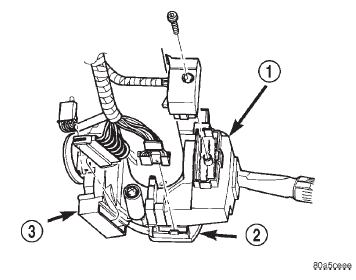 Fig. 8 Multi-function Switch & Column Wiring
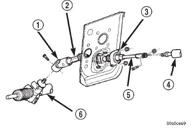 Fig. 9 Column Shafts & Couplers
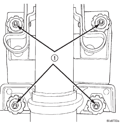 Fig. 10 Column Mounting Nuts
Gear shift lever
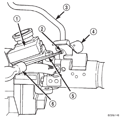 Fig. 11 Gear Shift Lever Removal
Dodge Durango (DN) 1998-2003 Service Manual
- Lubrication and Maintenance
- Suspension
- Differential and Driveline
- Brakes
- Cooling System
- Battery
- Starting Systems
- Charging System
- Ignition System
- Instrument Panel Systems
- Audio Systems
- Horn Systems
- Speed Control System
- Turn Signal and Hazard Warning Systems
- Wiper and Washer Systems
- Lamps
- Passive Restraint Systems
- Electrically Heated Systems
- Power Distribution System
- Power Lock Systems
- Vehicle Theft/Security Systems
- Power Seat System
- Power Window Systems
- Power Mirror Systems
- Chime/Buzzer Warning Systems
- Overhead Console Systems
- Engine
- Exhaust System
- Frame and Bumpers
- Fuel System
- Steering
- Transmission and Transfer Case
- Tires and Wheels
- Body
- Heating and Air Conditioning
- Emission Control Systems
- Introduction
Categories
