Valve body
Remove the valve body from the transmission, refer to Removal and Installation procedures section in this group.
DISASSEMBLY
CAUTION: Do not clamp any valve body component in a vise. This practice can damage the component resulting in unsatisfactory operation after assembly and installation. Do not use pliers to remove any of the valves, plugs or springs and do not force any of the components out or into place.
The valves and valve body housings will be damaged if force is used. Tag or mark the valve body springs for reference as they are removed. Do not allow them to become intermixed.
(1) Remove fluid filter.
(2) Disconnect wires from governor pressure sensor and solenoid.
(3) Remove screws attaching governor body and retainer plate to transfer plate.
(4) Remove retainer plate, governor body and gasket from transfer plate.
(5) Remove governor pressure sensor from governor body (6) Remove governor pressure solenoid by pulling it straight out of bore in governor body. Remove and discard solenoid O-rings if worn, cut, or torn.
(7) Remove small shoulder bolt that secures solenoid harness case connector to 3-4 accumulator housing (Fig. 99). Retain shoulder bolt. Either tape it to harness or thread it back into accumulator housing after connector removal.
(8) Unhook overdrive/converter solenoid harness from 3-4 accumulator cover plate (Fig. 100).
(9) Turn valve body over and remove screws that attach overdrive/converter solenoid assembly to valve body (Fig. 101).
(10) Remove solenoid and harness assembly from valve body (Fig. 102).
(11) Remove boost valve cover (Fig. 103).
(12) Remove boost valve retainer, valve spring and boost valve (Fig. 104).
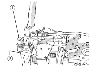 Fig. 99 Solenoid Harness Case Connector Shoulder Bolt
1 - SOLENOID HARNESS CASE CONNECTOR
2 - 3-4 ACCUMULATOR HOUSING
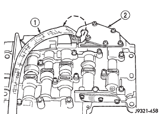 Fig. 100 Unhooking Solenoid Harness From Accumulator Cover Plate
1 - OVERDRIVE/CONVERTER SOLENOID WIRE HARNESS
2 - 3-4 ACCUMULATOR COVER PLATE
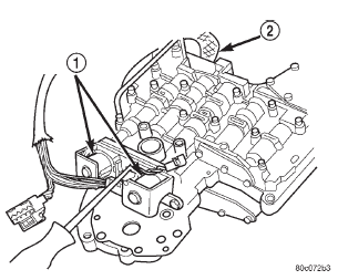 Fig. 101 Solenoid Assembly Screws
1 - OVERDRIVE/CONVERTER CLUTCH SOLENOID ASSEMBLY
2 - HARNESS
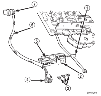 Fig. 102 Solenoid Assembly
1 - GOVERNOR SOLENOID WIRES
2 - CONVERTER CLUTCH SOLENOID
3 - SOLENOID SCREWS
4 - GOVERNOR SENSOR WIRES
5 - OVERDRIVE SOLENOID
6 - HARNESS
7 - CASE CONNECTOR
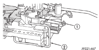 Fig. 103 Boost Valve Cover Location
1 - BOOST VALVE HOUSING AND COVER
2 - BOOST VALVE TUBE
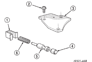 Fig. 104 Boost Valve Components
1 - SPRING AND VALVE RETAINER
2 - COVER SCREWS
3 - BOOST VALVE COVER
4 - BOOST VALVE PLUG
5 - BOOST VALVE
6 - BOOST VALVE SPRING
(13) Secure detent ball and spring with Retainer Tool 6583 (Fig. 105).
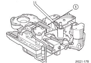 Fig. 105 Detent Ball And Spring
1 - SPECIAL TOOL 6583 POSITIONED ON DETENT HOUSING
(14) Remove park rod E-clip and separate rod from manual lever (Fig. 106).
(15) Remove E-clip and washer that retains throttle lever shaft in manual lever (Fig. 107).
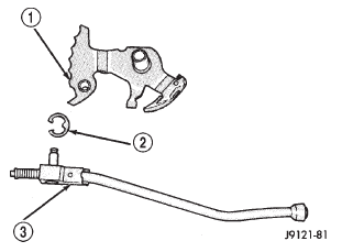 Fig. 106 Park Rod
1 - MANUAL LEVER
2 - E-CLIP
3 - PARK ROD
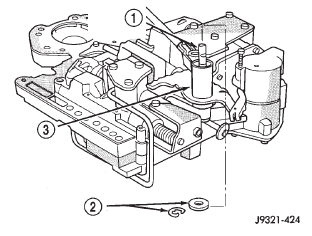 Fig. 107 Throttle Lever E-Clip And Washer
1 - THROTTLE LEVER SHAFT
2 - E-CLIP AND WASHER
3 - MANUAL SHAFT
(16) Remove manual lever and throttle lever (Fig.
108). Rotate and lift manual lever off valve body and throttle lever shaft. Then slide throttle lever out of valve body.
(17) Position pencil magnet next to detent housing to catch detent ball and spring. Then carefully remove Retainer Tool 6583 and remove detent ball and spring (Fig. 109).
(18) Remove screws attaching pressure adjusting screw bracket to valve body and transfer plate (Fig.
110). Hold bracket firmly against spring tension while removing last screw.
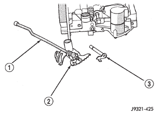 Fig. 108 Manual And Throttle Lever
1 - PARK ROD
2 - MANUAL LEVER ASSEMBLY
3 - THROTTLE LEVER
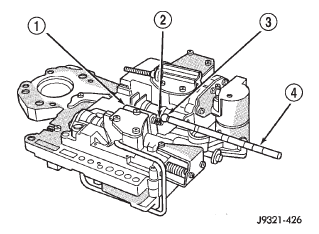 Fig. 109 Detent Ball And Spring
1 - DETENT HOUSING
2 - DETENT SPRING
3 - DETENT BALL
4 - PENCIL MAGNET
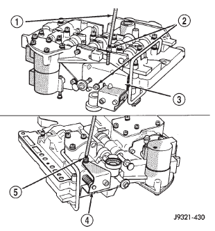 Fig. 110 Adjusting Screw Bracket Fastener
1 - T25 TORX BIT
2 - REMOVE THESE SCREWS FIRST
3 - BRACKET
4 - BRACKET
5 - REMOVE THIS SCREW LAST
(19) Remove adjusting screw bracket, line pressure adjusting screw, pressure regulator valve spring and switch valve spring (Fig. 111). Do not remove throttle pressure adjusting screw from bracket and do not disturb setting of either adjusting screw during removal.
(20) Turn upper housing over and remove switch valve, regulator valve and spring, and manual valve (Fig. 112).
(21) Remove kickdown detent, kickdown valve, and throttle valve and spring (Fig. 112).
(22) Loosen left-side 3-4 accumulator housing attaching screw about 2-3 threads. Then remove center and right-side housing attaching screws (Fig.
113).
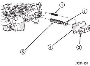 Fig. 111 Adjusting Screw Bracket And Spring
1 - SWITCH VALVE SPRING
2 - LINE PRESSURE SCREW
3 - THROTTLE PRESSURE ADJUSTING SCREW
4 - ADJUSTING SCREW BRACKET
5 - PRESSURE REGULATOR VALVE SPRING
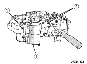 Fig. 113 Accumulator Housing Screw Locations
1 - LOOSEN THIS SCREW
2 - REMOVE THESE SCREWS
3 - 3-4 ACCUMULATOR HOUSING
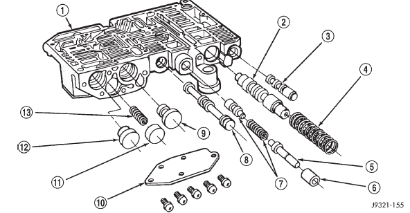 Fig. 112 Upper Housing Control Valve Locations
1 - UPPER HOUSING 2 - REGULATOR VALVE
3 - SWITCH VALVE
4 - REGULATOR VALVE SPRING
5 - KICKDOWN VALVE
6 - KICKDOWN DETENT
7 - THROTTLE VALVE AND SPRING
8 - MANUAL VALVE
9 - 1-2 GOVERNOR PLUG
10 - GOVERNOR PLUG COVER
11 - THROTTLE PLUG
12 - 2-3 GOVERNOR PLUG
13 - SHUTTLE VALVE PRIMARY SPRING
(23) Carefully rotate 3-4 accumulator housing upward and remove 3-4 shift valve spring and converter clutch valve plug and spring (Fig. 114).
(24) Remove left-side screw and remove 3-4 accumulator housing from valve body (Fig. 115).
(25) Bend back tabs on boost valve tube brace (Fig.
116).
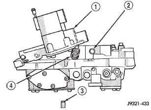 Fig. 114 3-4 Shift And Converter Clutch Valve Springs And Plug
1 - ACCUMULATOR HOUSING
2 - CONVERTER CLUTCH VALVE SPRING
3 - CLUTCH VALVE PLUG
4 - 3-4 SHIFT VALVE SPRING
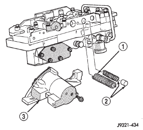 Fig. 115 Accumulator Housing, Valve Springs And Plug
1 - 3-4 SHIFT VALVE SPRING
2 - CONVERTER CLUTCH VALVE SPRING AND PLUG
3 - 3-4 ACCUMULATOR HOUSING
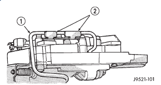 Fig. 116 Boost Valve Tube Brace
1 - BOOST VALVE TUBE
2 - TUBE BRACE (DOUBLE TAB)
(26) Remove boost valve connecting tube (Fig. 117).
Disengage tube from upper housing port first. Then rock opposite end of tube back and forth to work it out of lower housing.
CAUTION: Do not use tools to loosen or pry the connecting tube out of the valve body housings.
Loosen and remove the tube by hand only.
(27) Turn valve body over so lower housing is facing upward (Fig. 118). In this position, the two check balls in upper housing will remain in place and not fall out when lower housing and separator plate are removed.
(28) Remove screws attaching valve body lower housing to upper housing and transfer plate (Fig.
118). Note position of boost valve tube brace for assembly reference.
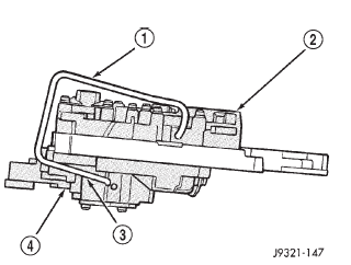 Fig. 117 Boost Valve Tube
1 - BOOST VALVE TUBE
2 - LOWER HOUSING
3 - DISENGAGE THIS END OF TUBE FIRST
4 - UPPER HOUSING
(29) Remove lower housing and overdrive separator plate from transfer plate (Fig. 118).
(30) Remove the ECE check ball from the transfer plate (Fig. 119). The ECE check ball is approximately 4.8 mm (3/16 in.) in diameter.
(31) Remove transfer plate from upper housing (Fig. 120).
(32) Turn transfer plate over so upper housing separator plate is facing upward.
(33) Remove upper housing separator plate from transfer plate (Fig. 121). Note position of filter in separator plate for assembly reference.
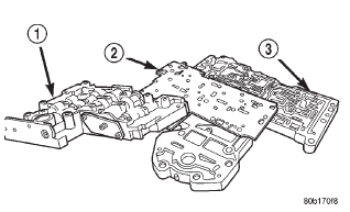 Fig. 118 Lower Housing
1 - LOWER HOUSING
2 - OVERDRIVE SEPARATOR PLATE
3 - TRANSFER PLATE AND UPPER HOUSING
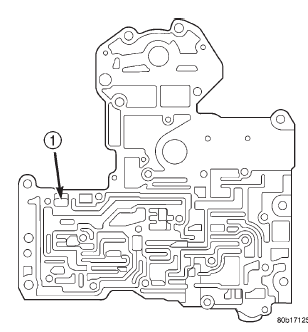 Fig. 119 ECE Check Ball
1 - ECE CHECK BALL (3/16")
(34) Remove rear clutch and rear servo check balls from transfer plate. Note check ball location for assembly reference (Fig. 122).
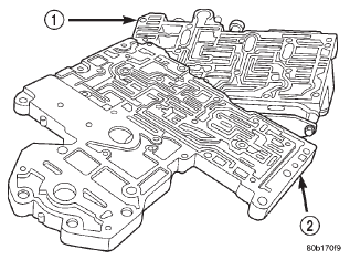 Fig. 120 Transfer Plate
1 - UPPER HOUSING
2 - TRANSFER PLATE
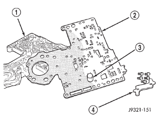 Fig. 121 Upper Housing Separator Plate
1 - TRANSFER PLATE
2 - UPPER HOUSING SEPARATOR PLATE
3 - FILTER SCREEN
4 - BRACE
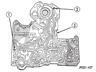 Fig. 122 Rear Clutch And Rear Servo Check Ball Locations
1 - REAR CLUTCH CHECK BALL
2 - REAR SERVO CHECK BALL
3 - TRANSFER PLATE
VALVE BODY UPPER HOUSING
(1) Note location of check balls in valve body upper housing (Fig. 123). Then remove the one large diameter and the six smaller diameter check balls.
(2) Remove governor plug and shuttle valve covers (Fig. 125).
(3) Remove E-clip that secures shuttle valve secondary spring on valve stem (Fig. 124).
(4) Remove throttle plug, primary spring, shuttle valve, secondary spring, and spring guides (Fig. 125).
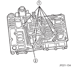 Fig. 123 Check Ball Locations In Upper Housing
1 - SMALL DIAMETER CHECK BALLS (6)
2 - LARGE DIAMETER CHECK BALL (1)
(5) Remove boost valve retainer, spring and valve if not previously removed.
(6) Remove throttle plug and 1-2 and 2-3 governor plugs (Fig. 112).
(7) Turn upper housing around and remove limit valve and shift valve covers (Fig. 126).
(8) Remove limit valve housing. Then remove retainer, spring, limit valve, and 2-3 throttle plug from limit valve housing (Fig. 126).
(9) Remove 1-2 shift control valve and spring (Fig.
126).
(10) Remove 1-2 shift valve and spring (Fig. 126).
(11) Remove 2-3 shift valve and spring from valve body (Fig. 126).
(12) Remove pressure plug cover (Fig. 126).
(13) Remove line pressure plug, sleeve, throttle pressure plug and spring (Fig. 126).
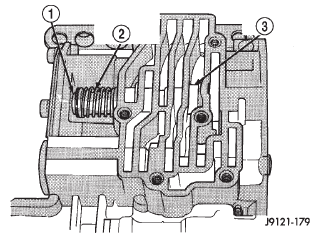 Fig. 124 Shuttle Valve E-Clip And Secondary Spring Location
1 - E-CLIP
2 - SECONDARY SPRING AND GUIDES
3 - SHUTTLE VALVE
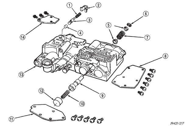 Fig. 125 Shuttle And Boost Valve Components
1 - SPRING
2 - RETAINER
3 - BOOST VALVE
4 - BOOST VALVE PLUG
5 - SPRING GUIDES
6 - E-CLIP
7 - SHUTTLE VALVE SECONDARY SPRING
8 - SHUTTLE VALVE COVER
9 - SHUTTLE VALVE
10 - SHUTTLE VALVE PRIMARY SPRING
11 - GOVERNOR PLUG COVER
12 - THROTTLE PLUG
13 - UPPER HOUSING
14 - BOOST VALVE COVER
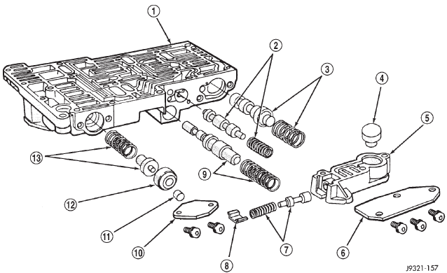 Fig. 126 Upper Housing Shift Valve And Pressure Plug Locations
1 - UPPER HOUSING
2 - 1-2 SHIFT VALVE AND SPRING
3 - 2-3 SHIFT VALVE AND SPRING
4 - 2-3 THROTTLE PLUG
5 - LIMIT VALVE HOUSING
6 - LIMIT VALVE COVER
7 - LIMIT VALVE AND SPRING
8 - RETAINER
9 - 1-2 SHIFT CONTROL VALVE AND SPRING
10 - PRESSURE PLUG COVER
11 - LINE PRESSURE PLUG
12 - PLUG SLEEVE
13 - THROTTLE PRESSURE SPRING AND PLUG
VALVE BODY LOWER HOUSING
(1) Remove timing valve cover.
(2) Remove 3-4 timing valve and spring.
(3) Remove 3-4 quick fill valve, spring and plug.
(4) Remove 3-4 shift valve and spring.
(5) Remove converter clutch valve, spring and plug (Fig. 127).
(6) Remove converter clutch timing valve, retainer and valve spring.
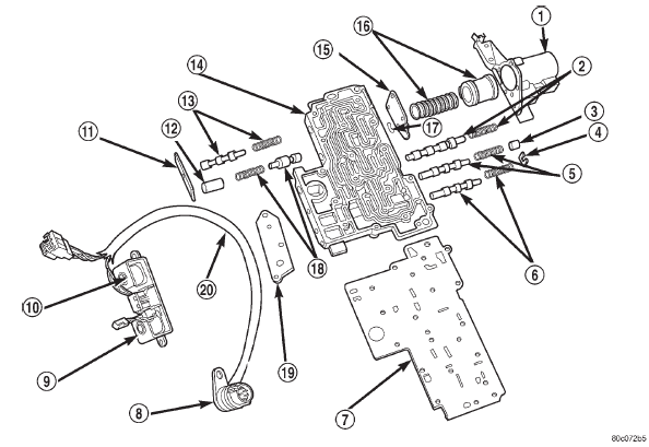 Fig. 127 Lower Housing Shift Valves And Springs
1 - 3-4 ACCUMULATOR HOUSING
2 - 3-4 SHIFT VALVE AND SPRING
3 - PLUG
4 - SPRING RETAINER
5 - CONVERTER CLUTCH VALVE AND SPRING
6 - CONVERTER CLUTCH TIMING VALVE AND SPRING
7 - OVERDRIVE SEPARATOR PLATE
8 - CASE CONNECTOR
9 - CONVERTER CLUTCH SOLENOID
10 - OVERDRIVE SOLENOID
11 - TIMING VALVE COVER
12 - PLUG
13 - 3-4 TIMING VALVE AND SPRING
14 - LOWER HOUSING
15 - ACCUMULATOR END PLATE
16 - 3-4 ACCUMULATOR PISTON AND SPRING
17 - E-CLIP
18 - 3-4 QUICK FILL SPRING AND VALVE
19 - SOLENOID GASKET
20 - HARNESS
3-4 ACCUMULATOR HOUSING
(1) Remove end plate from housing.
(2) Remove piston spring.
(3) Remove piston. Remove and discard piston seals (Fig. 128).
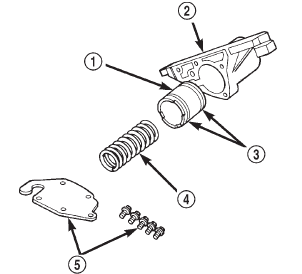 Fig. 128 Accumulator Housing Components
1 - ACCUMULATOR PISTON
2 - 3-4 ACCUMULATOR HOUSING
3 - TEFLON SEALS
4 - PISTON SPRING
5 - COVER PLATE AND SCREWS
ASSEMBLY
CAUTION: Do not force valves or plugs into place during reassembly. If the valve body bores, valves and plugs are free of distortion or burrs, the valve body components should all slide into place easily. In addition, do not overtighten the transfer plate and valve body screws during reassembly. Overtightening can distort the housings resulting in valve sticking, cross leakage and unsatisfactory operation. Tighten valve body screws to recommended torque only.
LOWER HOUSING
(1) Lubricate valves, springs, and the housing valve and plug bores with clean transmission fluid (Fig. 127).
(2) Install 3-4 timing valve spring and valve in lower housing.
(3) Install 3-4 quick fill valve in lower housing.
(4) Install 3-4 quick fill valve spring and plug in housing.
(5) Install timing valve end plate. Tighten end plate screws to 4 N*m (35 in. lbs.) torque.
3-4 ACCUMULATOR
(1) Lubricate accumulator piston, seals and housing piston bore with clean transmission fluid (Fig. 128).
(2) Install new seal rings on accumulator piston.
(3) Install piston and spring in housing.
(4) Install end plate on housing.
TRANSFER PLATE
(1) Install rear clutch and rear servo check balls in transfer plate (Fig. 129).
(2) Install filter screen in upper housing separator plate (Fig. 130).
(3) Align and position upper housing separator plate on transfer plate (Fig. 131).
(4) Install brace plate (Fig. 131). Tighten brace attaching screws to 4 N*m (35 in. lbs.) torque.
(5) Install remaining separator plate attaching screws. Tighten screws to 4 N*m (35 in. lbs.) torque.
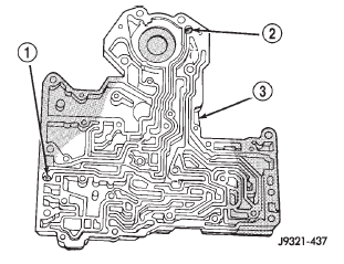 Fig. 129 Rear Clutch And Rear Servo Check Ball Locations
1 - REAR CLUTCH CHECK BALL
2 - REAR SERVO CHECK BALL
3 - TRANSFER PLATE
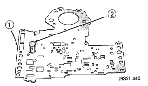 Fig. 130 Separator Plate Filter Screen Installation
1 - UPPER HOUSING SEPARATOR PLATE
2 - FILTER SCREEN
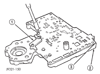 Fig. 131 Brace Plate
1 - BRACE
2 - TRANSFER PLATE
3 - SEPARATOR PLATE
UPPER AND LOWER HOUSING
(1) Position upper housing so internal passages and check ball seats are facing upward. Then install check balls in housing (Fig. 132). Eight check balls are used. The single large check ball is approximately 8.7 mm (11/32 in.) diameter. The single small check ball is approximately 4.8 mm (3/16 in.) in diameter. The remaining 6 check balls are approximately 6.3 mm (1/4 in.) in diameter.
(2) Position assembled transfer plate and upper housing separator plate on upper housing (Fig. 133).
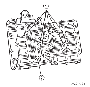 Fig. 132 Check Ball Locations In Upper Housing
1 - SMALL DIAMETER CHECK BALLS (6)
2 - LARGE DIAMETER CHECK BALL (1)
Be sure filter screen is seated in proper housing recess.
(3) Install the ECE check ball into the transfer plate (Fig. 119). The ECE check ball is approximately 4.8 mm (3/16 in.) in diameter.
(4) Position lower housing separator plate on transfer plate (Fig. 134).
(5) Install lower housing on assembled transfer plate and upper housing (Fig. 135).
(6) Install and start all valve body screws by hand except for the screws to hold the boost valve tube brace. Save those screws for later installation. Then tighten screws evenly to 4 N*m (35 in. lbs.) torque.
Start at center and work out to sides when tightening screws (Fig. 135).
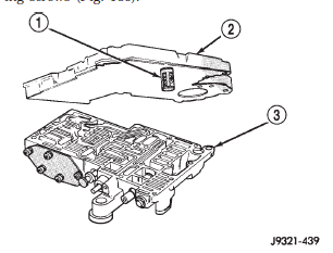 Fig. 133 Installing Transfer Plate On Upper Housing
1 - FILTER SCREEN
2 - TRANSFER PLATE/SEPARATOR PLATE ASSEMBLY
3 - UPPER HOUSING
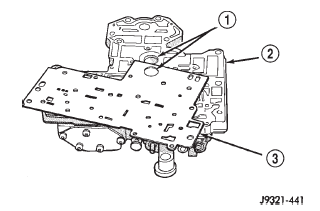 Fig. 134 Lower Housing Separator Plate
1 - BE SURE TO ALIGN BORES
2 - TRANSFER PLATE
3 - LOWER HOUSING (OVERDRIVE) SEPARATOR PLATE
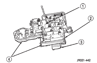 Fig. 135 Installing Lower Housing On Transfer Plate And Upper Housing
1 - VALVE BODY SCREWS (13)
2 - LOWER HOUSING
3 - UPPER HOUSING
4 - TRANSFER PLATE
UPPER HOUSING VALVE AND PLUG
Refer to (Fig. 136), (Fig. 137) and (Fig. 138) to perform the following steps.
(1) Lubricate valves, plugs, springs with clean transmission fluid.
(2) Assemble regulator valve line pressure plug, sleeve, throttle plug and spring. Insert assembly in upper housing and install cover plate. Tighten cover plate screws to 4 N*m (35 in. lbs.) torque.
(3) Install 1-2 and 2-3 shift valves and springs.
(4) Install 1-2 shift control valve and spring.
(5) Install retainer, spring, limit valve, and 2-3 throttle plug from limit valve housing.
(6) Install limit valve housing and cover plate.
Tighten screws to 4 N*m (35 in. lbs.).
(7) Install shuttle valve as follows: (a) Insert plastic guides in shuttle valve secondary spring and install spring on end of valve.
(b) Install shuttle valve into housing.
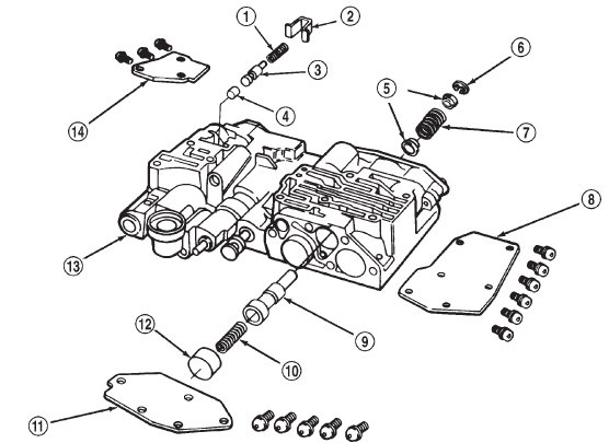 Fig. 136 Shuttle And Boost Valve Components
1 - SPRING
2 - RETAINER
3 - BOOST VALVE
4 - BOOST VALVE PLUG
5 - SPRING GUIDES
6 - E-CLIP
7 - SHUTTLE VALVE SECONDARY SPRING
8 - SHUTTLE VALVE COVER
9 - SHUTTLE VALVE
10 - SHUTTLE VALVE PRIMARY SPRING
11 - GOVERNOR PLUG COVER
12 - THROTTLE PLUG
13 - UPPER HOUSING
14 - BOOST VALVE COVER
(c) Hold shuttle valve in place.
(d) Compress secondary spring and install E-clip in groove at end of shuttle valve.
(e) Verify that spring and E-clip are properly seated before proceeding.
(8) Install shuttle valve cover plate. Tighten cover plate screws to 4 N*m (35 in. lbs.) torque.
(9) Install 1-2 and 2-3 valve governor plugs in valve body.
(10) Install shuttle valve primary spring and throttle plug.
(11) Align and install governor plug cover. Tighten cover screws to 4 N*m (35 in. lbs.) torque.
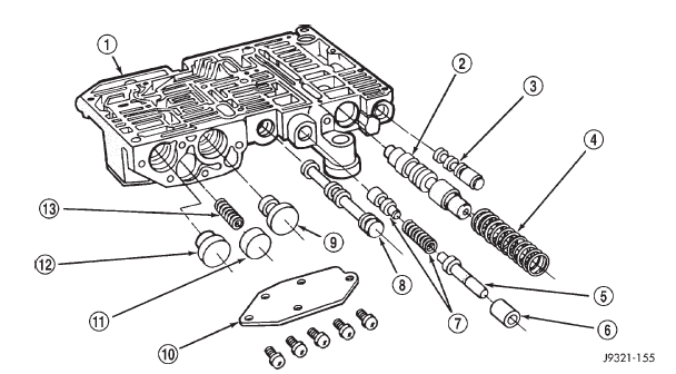 Fig. 137 Upper Housing Control Valve Locations
1 - UPPER HOUSING
2 - REGULATOR VALVE
3 - SWITCH VALVE
4 - REGULATOR VALVE SPRING
5 - KICKDOWN VALVE
6 - KICKDOWN DETENT
7 - THROTTLE VALVE AND SPRING
8 - MANUAL VALVE
9 - 1-2 GOVERNOR PLUG
10 - GOVERNOR PLUG COVER
11 - THROTTLE PLUG
12 - 2-3 GOVERNOR PLUG
13 - SHUTTLE VALVE PRIMARY SPRING
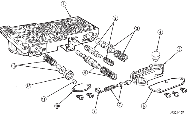 Fig. 138 Upper Housing Shift Valve And Pressure Plug Locations
1 - UPPER HOUSING
2 - 1-2 SHIFT VALVE AND SPRING
3 - 2-3 SHIFT VALVE AND SPRING
4 - 2-3 THROTTLE PLUG
5 - LIMIT VALVE HOUSING
6 - LIMIT VALVE COVER
7 - LIMIT VALVE AND SPRING
8 - RETAINER
9 - 1-2 SHIFT CONTROL VALVE AND SPRING
10 - PRESSURE PLUG COVER
11 - LINE PRESSURE PLUG
12 - PLUG SLEEVE
13 - THROTTLE PRESSURE SPRING AND PLUG
BOOST VALVE TUBE AND BRACE
(1) Position valve body assembly so lower housing is facing upward (Fig. 139).
(2) Lubricate tube ends and housing ports with transmission fluid or petroleum jelly.
(3) Start tube in lower housing port first. Then swing tube downward and work opposite end of tube into upper housing port (Fig. 139).
(4) Insert and seat each end of tube in housings.
(5) Slide tube brace under tube and into alignment with valve body screw holes (Fig. 140).
(6) Install and finger tighten three screws that secure tube brace to valve body housings (Fig. 140).
(7) Bend tube brace tabs up and against tube to hold it in position (Fig. 141).
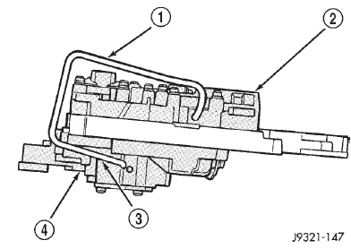 Fig. 139 Boost Valve Tube
1 - BOOST VALVE TUBE
2 - LOWER HOUSING
3 - DISENGAGE THIS END OF TUBE FIRST
4 - UPPER HOUSING
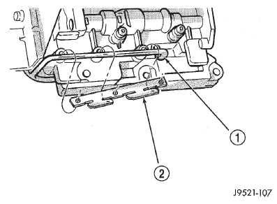 Fig. 140 Boost Valve Tube And Brace
1 - BOOST VALVE TUBE
2 - TUBE BRACE
(8) Tighten all valve body housing screws to 4 N*m (35 in. lbs.) torque after tube and brace are installed.
Tighten screws in diagonal pattern starting at center and working outward.
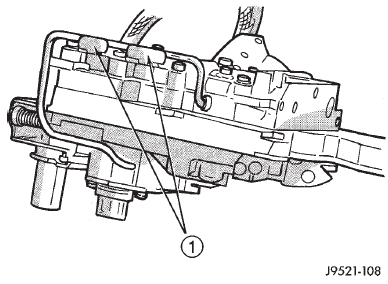 Fig. 141 Securing Boost Valve Tube With Brace Tabs
1 - BEND TABS UP AGAINST TUBE AS SHOWN
3-4 ACCUMULATOR
(1) Position converter clutch valve and 3-4 shift valve springs in housing (Fig. 142).
(2) Loosely attach accumulator housing with rightside screw (Fig. 142). Install only one screw at this time as accumulator must be free to pivot upward for ease of installation.
(3) Install 3-4 shift valve and spring.
(4) Install converter clutch timing valve and spring.
(5) Position plug on end of converter clutch valve spring. Then compress and hold springs and plug in place with fingers of one hand.
(6) Swing accumulator housing upward over valve springs and plug.
(7) Hold accumulator housing firmly in place and install remaining two attaching screws. Be sure springs and clutch valve plug are properly seated (Fig. 143). Tighten screws to 4 N*m (35 in. lbs.).
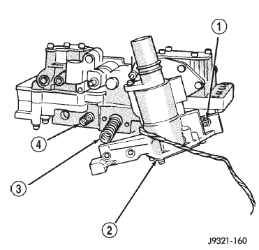 Fig. 142 Converter Clutch And 3-4 Shift Valve Springs
1 - RIGHT-SIDE SCREW
2 - 3-4 ACCUMULATOR
3 - 3-4 SHIFT VALVE SPRING
4 - CONVERTER CLUTCH VALVE SPRING
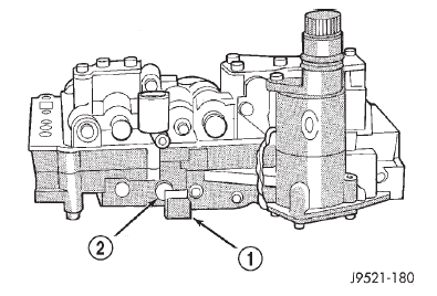 Fig. 143 Seating 3-4 Accumulator On Lower Housing
1 - ACCUMULATOR BOX
2 - CONVERTER CLUTCH VALVE PLUG
VALVE BODY FINAL
(1) Install boost valve, valve spring, retainer and cover plate. Tighten cover plate screws to 4 N*m (35 in. lbs.) torque.
(2) Insert manual lever detent spring in upper housing.
(3) Position detent ball on end of spring. Then hold detent ball and spring in detent housing with Retainer Tool 6583 (Fig. 144).
(4) Install throttle lever in upper housing. Then install manual lever over throttle lever and start manual lever into housing.
(5) Align manual lever with detent ball and manual valve. Hold throttle lever upward. Then press down on manual lever until fully seated. Remove detent ball retainer tool after lever is seated.
(6) Then install manual lever seal, washer and E-clip.
(7) Verify that throttle lever is aligned with end of kickdown valve stem and that manual lever arm is engaged in manual valve (Fig. 145).
(8) Position line pressure adjusting screw in adjusting screw bracket.
(9) Install spring on end of line pressure regulator valve.
(10) Install switch valve spring on tang at end of adjusting screw bracket.
(11) Install manual valve.
(12) Install throttle valve and spring.
(13) Install kickdown valve and detent.
(14) Install pressure regulator valve.
(15) Install switch valve.
(16) Position adjusting screw bracket on valve body. Align valve springs and press bracket into place. Install short, upper bracket screws first and long bottom screw last. Verify that valve springs and bracket are properly aligned. Then tighten all three bracket screws to 4 N*m (35 in. lbs.) torque.
(17) Perform Line Pressure and Throttle Pressure adjustments. Refer to adjustment section of this group for proper procedures.
(18) Lubricate solenoid case connector O-rings and shaft of manual lever with light coat of petroleum jelly.
(19) Attach solenoid case connector to 3-4 accumulator with shoulder-type screw. Connector has small locating tang that fits in dimple at top of accumulator housing (Fig. 146). Seat tang in dimple before tightening connector screw.
(20) Install solenoid assembly and gasket. Tighten solenoid attaching screws to 8 N*m (72 in. lbs.) torque.
(21) Verify that solenoid wire harness is properly routed (Fig. 147). Solenoid harness must be clear of manual lever and park rod and not be pinched between accumulator housing and cover.
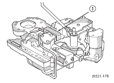 Fig. 144 Detent Ball Spring
1 - SPECIAL TOOL 6583 POSITIONED ON DETENT HOUSING
 Fig. 145 Manual And Throttle Lever Alignment
1 - THROTTLE LEVER
2 - MANUAL LEVER VALVE ARM
3 - MANUAL VALVE
4 - KICKDOWN VALVE
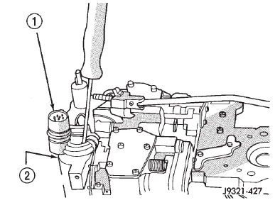 Fig. 146 Solenoid Harness Case Connector Shoulder Bolt
1 - SOLENOID HARNESS CASE CONNECTOR
2 - 3-4 ACCUMULATOR HOUSING
GOVERNOR BODY, SENSOR AND SOLENOID
(1) Turn valve body assembly over so accumulator side of transfer plate is facing down.
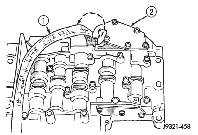 Fig. 147 Solenoid Harness Routing
1 - OVERDRIVE/CONVERTER SOLENOID WIRE HARNESS
2 - 3-4 ACCUMULATOR COVER PLATE
(2) Install new O-rings on governor pressure solenoid and sensor.
(3) Lubricate solenoid and sensor O-rings with clean transmission fluid.
(4) Install governor pressure sensor in governor body.
(5) Install governor pressure solenoid in governor body. Push solenoid in until it snaps into place in body.
(6) Position governor body gasket on transfer plate.
(7) Install retainer plate on governor body and around solenoid. Be sure solenoid connector is positioned in retainer cutout.
(8) Align screw holes in governor body and transfer plate. Then install and tighten governor body screws to 4 N*m (35 in. lbs.) torque.
(9) Connect harness wires to governor pressure solenoid and governor pressure sensor.
(10) Install fluid filter and pan.
(11) Lower vehicle.
(12) Fill transmission with recommended fluid and road test vehicle to verify repair.
Dodge Durango (DN) 1998-2003 Service Manual
- Lubrication and Maintenance
- Suspension
- Differential and Driveline
- Brakes
- Cooling System
- Battery
- Starting Systems
- Charging System
- Ignition System
- Instrument Panel Systems
- Audio Systems
- Horn Systems
- Speed Control System
- Turn Signal and Hazard Warning Systems
- Wiper and Washer Systems
- Lamps
- Passive Restraint Systems
- Electrically Heated Systems
- Power Distribution System
- Power Lock Systems
- Vehicle Theft/Security Systems
- Power Seat System
- Power Window Systems
- Power Mirror Systems
- Chime/Buzzer Warning Systems
- Overhead Console Systems
- Engine
- Exhaust System
- Frame and Bumpers
- Fuel System
- Steering
- Transmission and Transfer Case
- Tires and Wheels
- Body
- Heating and Air Conditioning
- Emission Control Systems
- Introduction
