Service procedures
SUSPENSION HEIGHT - 4x4
The vehicle suspension height should be measured and adjusted if necessary before performing wheel alignment procedure. Also when front suspension components have been replaced. This measure must be performed with the vehicle supporting it's own weight and taken on both sides of the vehicle.
HEIGHT MEASUREMENT
(1) Jounce the front of the vehicle.
(2) Measure and record the distance between the ground and the center of the lower suspension arm rear mounting bolt head (Fig. 2).
(3) Measure and record the distance between the ground and the center of the front wheel (Fig. 2).
(4) Subtract the first measurement from the second measurement. The difference between the two measurement should be 73 mm (2.9 inches) 6 3 mm (0.12 inches).
HEIGHT ADJUSTMENT
To adjust the vehicle height turn the torsion bar adjustment bolt CLOCKWISE to raise the vehicle and COUNTER CLOCKWISE to lower the vehicle.
CAUTION: ALWAYS raise the vehicle to the correct suspension height, NEVER lower the vehicle to obtain the correct suspension height. If the vehicle suspension height is too high, lower the vehicle below the height specification. Then raise the vehicle to the correct suspension height specification.
This will insure the vehicle maintains the proper suspension height.
 Fig. 2 Height Measurement
NOTE: If a height adjustment has been made, perform height measurement again on both sides of the vehicle.
WHEEL ALIGNMENT
NOTE: 4x4 suspension height measurement must be performed before alignment.
CAMBER AND CASTER ADJUSTMENT
Camber and caster angle adjustments involve changing the position of the upper suspension arm pivot bar (Fig. 3).
 Fig. 3 Caster & Camber Adjustment-Typical
1 - PIVOT BAR
2 - + CASTER
3 - + CAMBER
4 - UPPER ARM SUSPENSION
NOTE: On 4x2 vehicles use Alignment Tool 8393 for alignment. The tool attaches to the pivot bar on the upper control arm.
CASTER
Moving the rear position of the pivot bar in or out, will change the caster angle significantly and camber angle only slightly. To maintain the camber angle while adjusting caster, move the rear of the pivot bar in or out. Then move the front of the pivot bar slightly in the opposite direction.
To increase positive caster angle, move the rear position of the pivot bar inward (toward the engine).
Move the front of pivot bar outward (away from the engine) slightly until the original camber angle is obtained.
CAMBER
Move the front of the pivot bar in or out. This will change the camber angle significantly and caster angle slightly.
After adjustment is made tighten the pivot bar nuts to proper torque specification.
TOE ADJUSTMENT
The wheel toe position adjustment is the final adjustment.
(1) Start the engine and turn wheels both ways before straightening the wheels. Secure the steering wheel with the front wheels in the straight-ahead position.
(2) Loosen the tie rod jam nuts.
NOTE: Each front wheel should be adjusted for one-half of the total toe position specification. This will ensure the steering wheel will be centered when the wheels are positioned straight-ahead.
(3) Adjust the wheel toe position by turning the tie rod as necessary (Fig. 4).
 Fig. 4 Toe Adjustment
1 - JAM NUT
2 - TIE ROD
3 - TIE ROD END
(4) Tighten the tie rod jam nut to 75 N*m (55 ft.
lbs.).
(5) Verify the specifications (6) Turn off engine.
Specifications
ALIGNMENT
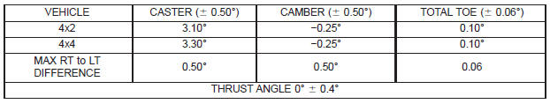
NOTE: All alignment specifications are in degrees.
Dodge Durango (DN) 1998-2003 Service Manual
- Lubrication and Maintenance
- Suspension
- Differential and Driveline
- Brakes
- Cooling System
- Battery
- Starting Systems
- Charging System
- Ignition System
- Instrument Panel Systems
- Audio Systems
- Horn Systems
- Speed Control System
- Turn Signal and Hazard Warning Systems
- Wiper and Washer Systems
- Lamps
- Passive Restraint Systems
- Electrically Heated Systems
- Power Distribution System
- Power Lock Systems
- Vehicle Theft/Security Systems
- Power Seat System
- Power Window Systems
- Power Mirror Systems
- Chime/Buzzer Warning Systems
- Overhead Console Systems
- Engine
- Exhaust System
- Frame and Bumpers
- Fuel System
- Steering
- Transmission and Transfer Case
- Tires and Wheels
- Body
- Heating and Air Conditioning
- Emission Control Systems
- Introduction
Categories
