Refrigerant system service equipment. Vacuum system
WARNING: EYE PROTECTION MUST BE WORN
WHEN SERVICING AN AIR CONDITIONING REFRIGERANT
SYSTEM. TURN OFF (ROTATE CLOCKWISE)
ALL VALVES ON THE EQUIPMENT BEING USED,
BEFORE CONNECTING TO OR DISCONNECTING
FROM THE REFRIGERANT SYSTEM. FAILURE TO
OBSERVE THESE WARNINGS MAY RESULT IN PERSONAL
INJURY. When servicing the air conditioning system, a
R-134a refrigerant recovery/recycling/charging station
that meets SAE Standard J2210 must be used.
Contact an automotive service equipment supplier for
refrigerant recovery/recycling/charging equipment.
Refer to the operating instructions supplied by the
equipment manufacturer for the proper care and use
of this equipment.
A manifold gauge set may be needed with some
recovery/recycling/charging equipment (Fig. 9). The
service hoses on the gauge set being used should
have manual (turn wheel), or automatic back-flow
valves at the service port connector ends. This will
prevent refrigerant from being released into the
atmosphere. MANIFOLD GAUGE SET CONNECTIONS CAUTION: Do not use an R-12 manifold gauge set
on an R-134a system. The refrigerants are not compatible
and system damage will result. LOW PRESSURE GAUGE HOSE The low pressure hose (Blue with Black stripe)
attaches to the suction service port. This port is
located on the compressor manifold, directly over the
suction port of the compressor. HIGH PRESSURE GAUGE HOSE The high pressure hose (Red with Black stripe)
attaches to the discharge service port. This port is
located on the liquid line between the condenser and
the evaporator, near the front of the engine compartment. RECOVERY/RECYCLING/EVACUATION/CHARGING HOSE The center manifold hose (Yellow, or White, with
Black stripe) is used to recover, evacuate, and charge
the refrigerant system. When the low or high pressure
valves on the manifold gauge set are opened,
the refrigerant in the system will escape through this
hose.
1 - HIGH PRESSURE GAUGE 2 - VALVE 3 - VACUUM/REFRIGERANT HOSE (YELLOW W/BLACK
STRIPE) 4 - HIGH PRESSURE HOSE (RED W/BLACK STRIPE) 5 - LOW PRESSURE HOSE (BLUE W/BLACK STRIPE) 6 - VALVE 7 - LOW PRESSURE GAUGE Vacuum control is used to operate the mode doors
in the heater-A/C housing. Testing of the heater-A/C
mode control switch operation will determine if the
vacuum, electrical, and mechanical controls are functioning.
However, it is possible that a vacuum control
system that operates perfectly at engine idle (high
engine vacuum) may not function properly at high
engine speeds or loads (low engine vacuum). This can
be caused by leaks in the vacuum system, or by a
faulty or improperly installed vacuum check valve.
A vacuum system test will help to identify the
source of poor vacuum system performance or vacuum
system leaks. Before starting this test, stop the
engine and make certain that the problem is not a
disconnected vacuum supply tube at the engine vacuum
source or at the vacuum reservoir.
Use an adjustable vacuum test set (Special Tool
C-3707-B) and a suitable vacuum pump to test the
heater-A/C vacuum control system. With a finger
placed over the end of the vacuum test hose probe
(Fig. 10), adjust the bleed valve on the test set gauge
to obtain a vacuum of exactly 27 kPa (8 in. Hg.).
Release and block the end of the probe several times
to verify that the vacuum reading returns to the exact 27 kPa (8 in. Hg.)
setting. Otherwise, a false
reading will be obtained during testing.
1 - VACUUM PUMP TOOL C-4289 2 - VACUUM TEST SET C-3707 3 - BLEED VALVE 4 - PROBE VACUUM CHECK VALVE (1) Remove the vacuum check valve that is to be
tested. The valves are located in the vacuum supply
tube (black) at the power brake booster on the left
side of the engine compartment, and in the heater
and air conditioner vacuum take-out of the vacuum
supply tube in the engine compartment. The vacuum
check valve must be removed in order to perform the
following tests. See Vacuum Check Valve in the
Removal and Installation section of this group for the
procedures.
(2) Connect the test set vacuum supply hose to the
heater-A/C control side of the valve. When connected
to this side of the check valve, no vacuum should
pass and the test set gauge should return to the 27
kPa (8 in. Hg.) setting. If OK, go to step Step 3. If
not OK, replace the faulty valve.
(3) Connect the test set vacuum supply hose to the
engine vacuum side of the valve. When connected to
this side of the check valve, vacuum should flow
through the valve without restriction. If not OK,
replace the faulty valve. HEATER-A/C CONTROLS (1) Connect the test set vacuum probe to the heater-
A/C vacuum supply (black) tube in the engine
compartment. Position the test set gauge so that it
can be viewed from the passenger compartment.
(2) Place the heater-A/C mode control switch knob
in each mode position, one position at a time, and
pause after each selection. The test set gauge should return to the 27 kPa
(8 in. Hg.) setting shortly after
each selection is made. If not OK, a component or
vacuum line in the vacuum circuit of the selected
mode has a leak. See Locating Vacuum Leaks in the
Diagnosis and Testing section of this group. CAUTION: Do not use lubricant on the switch ports
or in the holes in the plug, as lubricant will ruin the
vacuum valve in the switch. A drop of clean water
in the connector plug holes will help the connector
slide onto the switch ports. LOCATING VACUUM LEAKS WARNING: ON VEHICLES EQUIPPED WITH AIRBAGS,
REFER TO GROUP 8M - PASSIVE
RESTRAINT SYSTEMS BEFORE ATTEMPTING ANY
STEERING WHEEL, STEERING COLUMN, OR
INSTRUMENT PANEL COMPONENT DIAGNOSIS OR
SERVICE. FAILURE TO TAKE THE PROPER PRECAUTIONS
COULD RESULT IN ACCIDENTAL AIRBAG
DEPLOYMENT AND POSSIBLE PERSONAL
INJURY. (1) Disconnect the vacuum harness connector from
the back of the heater-A/C mode control switch on
the instrument panel.
(2) Connect the test set vacuum hose probe to each
port in the vacuum harness connector, one port at a
time, and pause after each connection (Fig. 11). The
test set gauge should return to the 27 kPa (8 in. Hg.)
setting shortly after each connection is made. If OK,
replace the faulty heater-A/C control. If not OK, go to
Step 3.
(3) Determine the vacuum line color of the vacuum
circuit that is leaking. To determine the vacuum line
colors, see the Vacuum Circuits chart (Fig. 12).
(4) Disconnect and plug the vacuum line from the
component (fitting, actuator, valve, switch, or reservoir)
on the other end of the leaking circuit. Instrument
panel disassembly or removal may be necessary
to gain access to some components. See the Removal
and Installation section of this group for more information.
(5) Connect the test set hose or probe to the open
end of the leaking circuit. The test set gauge should
return to the 27 kPa (8 in. Hg.) setting shortly after
each connection is made. If OK, replace the faulty
disconnected component. If not OK, go to Step 6.
(6) To locate a leak in a vacuum line, leave one
end of the line plugged and connect the test set hose
or probe to the other end of the line. Run your fingers
slowly along the line while watching the test set
gauge. The vacuum reading will fluctuate when your
fingers contact the source of the leak. To repair the
vacuum line, cut out the leaking section of the line.
Then, insert the loose ends of the line into a suitable
length of 3 millimeter (0.125 inch) inside diameter
rubber hose.
Refrigerant system service equipment
 Fig. 9 Manifold Gauge Set - Typical
Vacuum system
 Fig. 10 Adjust Vacuum Test Bleed Valve
 Fig. 11 Vacuum Circuit Test
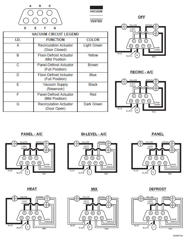 Fig. 12 Vacuum Circuits
Dodge Durango (DN) 1998-2003 Service Manual
- Lubrication and Maintenance
- Suspension
- Differential and Driveline
- Brakes
- Cooling System
- Battery
- Starting Systems
- Charging System
- Ignition System
- Instrument Panel Systems
- Audio Systems
- Horn Systems
- Speed Control System
- Turn Signal and Hazard Warning Systems
- Wiper and Washer Systems
- Lamps
- Passive Restraint Systems
- Electrically Heated Systems
- Power Distribution System
- Power Lock Systems
- Vehicle Theft/Security Systems
- Power Seat System
- Power Window Systems
- Power Mirror Systems
- Chime/Buzzer Warning Systems
- Overhead Console Systems
- Engine
- Exhaust System
- Frame and Bumpers
- Fuel System
- Steering
- Transmission and Transfer Case
- Tires and Wheels
- Body
- Heating and Air Conditioning
- Emission Control Systems
- Introduction
Categories
