Engine. Engine lubrication system
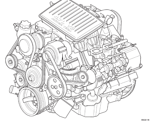
DESCRIPTION The 4.7 liter (287 CID) eight-cylinder engine is an
90 single overhead camshaft engine. The cast iron
cylinder block is made up of two different components;
the first component is the cylinder bore and
upper block, the second component is the bedplate
that comprises the lower portion of the cylinder block
and houses the lower half of the crankshaft main
bearings. The cylinders are numbered from front to
rear with the left bank being numbered 1,3,5 and 7,
and the right bank being numbered 2,4,6 and 8. The firing order is
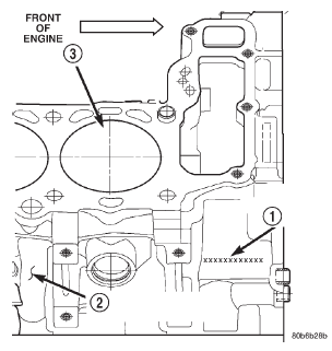
1-8-4-3-6-5-7-2. The engine serial
number is located at the right front side of the
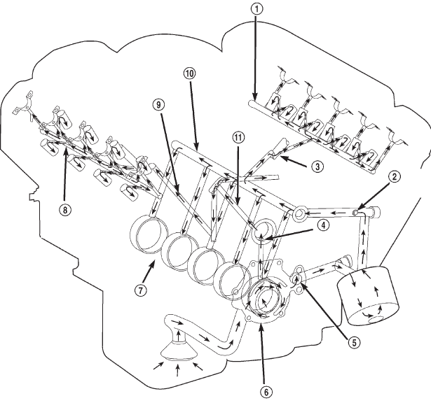
engine block (Fig. 1) DESCRIPTION The lubrication system (Fig. 2) is a full flow filtration
pressure feed type. OPERATION Oil from the oil pan is pumped by a gerotor type oil
pump directly mounted to the crankshaft nose. Oil
pressure is controlled by a relief valve mounted
inside the oil pump housing. For lubrication flow
refer to (Fig. 2).
The camshaft exhaust valve lobes and rocker arms
are lubricated through a small hole in the rocker
arm; oil flows through the lash adjuster then through
the rocker arm and onto the camshaft lobe. Due to
the orentation of the rocker arm, the camshaft intake
lobes are not lubed in the same manner as the
exhaust lobes. The intake lobes are lubed through
internal passages in the camshaft. Oil flows through
a bore in the number 3 camshaft bearing bore, and
as the camshaft turns, a hole in the camshaft aligns
with the hole in the camshaft bore allowing engine
oil to enter the camshaft tube. The oil then exits
through 1.6mm (0.063 in.) holes drilled into the
intake lobes, lubricating the lobes and the rocker
arms.
1 - VEHICLE VIN NUMBER LOCATION 2 - CYLINDER BLOCK RIGHT HAND SIDE 3 - CYLINDER BORE #2 ENGINE LUBRICATION FLOW CHART-BLOCK: TABLE 1 2. Left Cylinder Head* 3. Right Cylinder Head* 2. Both Secondary Chain
Tensioners
1 - LEFT CYLINDER HEAD OIL GALLERY 2 - OIL PRESSURE SENSOR LOCATION 3 - TO LEFT CYLINDER HEAD 4 - OIL FEED TO IDLER SHAFT 5 - OIL PUMP OUTLET TO BLOCK 6 - OIL PUMP 7 - TO CRANKSHAFT MAIN JOURNALS 8 - RIGHT CYLINDER HEAD OIL GALLERY 9 - TO RIGHT CYLINDER HEAD 10 - CYLINDER BLOCK MAIN GALLERY 11 - OIL FEED TO BOTH SECONDARY TENSIONERS ENGINE LUBRICATION FLOW CHART-CYLINDER HEADS: TABLE 2 2. Lash Adjuster TowersEngine

Engine lubrication system
 Fig. 1 Engine Identification Location.
FROM
TO
Oil Pickup Tube
Oil Pump
Oil Pump
Oil Filter
Oil Filter
Block Main Oil Gallery
Block Main Oil Gallery
1. Crankshaft Main Journal
Crankshaft Main Journals
Crankshaft Rod Journals
Crankshaft Number One Main Journal
1.Front Timing Chain Idler Shaft
Left Cylinder Head
See Table 2
Right Cylinder Head
See Table 2
* The cylinder head
gaskets have an oil restricter to control oil flow to the cylinder
heads.
 Fig. 2 Engine Oil Lubrication System
FROM
TO
Cylinder Head Oil Port (in bolt hole)
Diagonal Cross Drilling to Main Oil Gallery
Main Oil Gallery (drilled through head from rear to front)
1. Base of Camshaft Towers
Base of Camshaft Towers
Vertical Drilling Through Tower to Camshaft Bearings**
Lash Adjuster Towers
Diagonal Drillings to Hydraulic Lash Adjuster Pockets
** The number three camshaft bearing journal feeds oil
into the hollow camshaft tubes. Oil is routed to the intake
lobes, which have oil passages drilled into them to lubricate the rocker
arms.
Dodge Durango (DN) 1998-2003 Service Manual
- Lubrication and Maintenance
- Suspension
- Differential and Driveline
- Brakes
- Cooling System
- Battery
- Starting Systems
- Charging System
- Ignition System
- Instrument Panel Systems
- Audio Systems
- Horn Systems
- Speed Control System
- Turn Signal and Hazard Warning Systems
- Wiper and Washer Systems
- Lamps
- Passive Restraint Systems
- Electrically Heated Systems
- Power Distribution System
- Power Lock Systems
- Vehicle Theft/Security Systems
- Power Seat System
- Power Window Systems
- Power Mirror Systems
- Chime/Buzzer Warning Systems
- Overhead Console Systems
- Engine
- Exhaust System
- Frame and Bumpers
- Fuel System
- Steering
- Transmission and Transfer Case
- Tires and Wheels
- Body
- Heating and Air Conditioning
- Emission Control Systems
- Introduction
