Distributors-3.9/5.2/5.9L engines
REMOVAL
CAUTION: Base ignition timing is not adjustable on any engine. Distributors do not have built in centrifugal or vacuum assisted advance. Base ignition timing and timing advance are controlled by the Powertrain Control Module (PCM). Because a conventional timing light can not be used to adjust distributor position after installation, note position of distributor before removal.
(1) Remove air cleaner assembly.
(2) Disconnect negative cable from battery.
(3) Remove distributor cap from distributor (two screws).
(4) Mark the position of distributor housing in relationship to engine or dash panel. This is done to aid in installation.
(5) Before distributor is removed, the number one cylinder must be brought to the Top Dead Center (TDC) firing position.
(6) Attach a socket to the Crankshaft Vibration Damper mounting bolt.
(7) Slowly rotate engine clockwise, as viewed from front, until indicating mark on crankshaft vibration damper is aligned to 0 degree (TDC) mark on timing chain cover (Fig. 31).
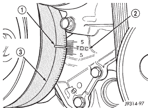 Fig. 31 Damper-To-Cover Alignment Marks-Typical
1 - ALIGNMENT MARK
2 - TIMING CHAIN COVER MARKS
3 - CRANKSHAFT VIBRATION DAMPER
(8) The distributor rotor should now be aligned to the CYL. NO. 1 alignment mark (stamped) into the camshaft position sensor (Fig. 32). If not, rotate the crankshaft through another complete 360 degree turn. Note the position of the number one cylinder spark plug cable (on the cap) in relation to rotor.
Rotor should now be aligned to this position.
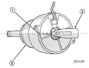 Fig. 32 Rotor Alignment Mark-3.9/5.2/5.9L Engines
1 - CAMSHAFT POSITION SENSOR ALIGNMENT MARK
2 - ROTOR
3 - DISTRIBUTOR
(9) Disconnect camshaft position sensor wiring harness from main engine wiring harness.
(10) Remove distributor rotor from distributor shaft.
(11) Remove distributor holddown clamp bolt and clamp (Fig. 33). Remove distributor from vehicle.
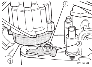 Fig. 33 Distributor Holddown Clamp-3.9/5.2/5.9L Engines
1 - CLAMP BOLT
2 - HOLDDOWN CLAMP
3 - DISTRIBUTOR HOUSING
CAUTION: Do not crank engine with distributor removed. Distributor/crankshaft relationship will be lost.
INSTALLATION
If engine has been cranked while distributor is removed, establish the relationship between distributor shaft and number one piston position as follows: Rotate crankshaft in a clockwise direction, as viewed from front, until number one cylinder piston is at top of compression stroke (compression should be felt on finger with number one spark plug removed). Then continue to slowly rotate engine clockwise until indicating mark (Fig. 31) is aligned to 0 degree (TDC) mark on timing chain cover.
(1) Clean top of cylinder block for a good seal between distributor base and block.
(2) Lightly oil the rubber o-ring seal on the distributor housing.
(3) Install rotor to distributor shaft.
(4) Position distributor into engine to its original position. Engage tongue of distributor shaft with slot in distributor oil pump drive gear. Position rotor to the number one spark plug cable position.
(5) Install distributor holddown clamp and clamp bolt. Do not tighten bolt at this time.
(6) Rotate the distributor housing until rotor is aligned to CYL. NO. 1 alignment mark on the camshaft position sensor (Fig. 32).
(7) Tighten clamp holddown bolt (Fig. 33) to 22.5 N*m (200 in. lbs.) torque.
(8) Connect camshaft position sensor wiring harness to main engine harness.
(9) Install distributor cap. Tighten mounting screws.
(10) Refer to the following, Checking Distributor Position.
CHECKING DISTRIBUTOR POSITION
To verify correct distributor rotational position, the DRB scan tool must be used.
WARNING: WHEN PERFORMING THE FOLLOWING TEST, THE ENGINE WILL BE RUNNING. BE CAREFUL NOT TO STAND IN LINE WITH THE FAN BLADES OR FAN BELT. DO NOT WEAR LOOSE CLOTHING.
(1) Connect DRB scan tool to data link connector.
The data link connector is located in passenger compartment, below and to left of steering column.
(2) Gain access to SET SYNC screen on DRB.
(3) Follow directions on DRB screen and start engine. Bring to operating temperature (engine must be in "closed loop" mode).
(4) With engine running at idle speed, the words IN RANGE should appear on screen along with 0.
This indicates correct distributor position.
(5) If a plus (+) or a minus (-) is displayed next to degree number, and/or the degree displayed is not zero, loosen but do not remove distributor holddown clamp bolt. Rotate distributor until IN RANGE appears on screen. Continue to rotate distributor until achieving as close to 0 as possible. After adjustment, tighten clamp bolt to 22.5 N*m (200 in.
lbs.) torque.
The degree scale on SET SYNC screen of DRB is referring to fuel synchronization only. It is not referring to ignition timing. Because of this, do not attempt to adjust ignition timing using this method. Rotating distributor will have no effect on ignition timing. All ignition timing values are controlled by powertrain control module (PCM).
After testing, install air cleaner assembly.
Dodge Durango (DN) 1998-2003 Service Manual
- Lubrication and Maintenance
- Suspension
- Differential and Driveline
- Brakes
- Cooling System
- Battery
- Starting Systems
- Charging System
- Ignition System
- Instrument Panel Systems
- Audio Systems
- Horn Systems
- Speed Control System
- Turn Signal and Hazard Warning Systems
- Wiper and Washer Systems
- Lamps
- Passive Restraint Systems
- Electrically Heated Systems
- Power Distribution System
- Power Lock Systems
- Vehicle Theft/Security Systems
- Power Seat System
- Power Window Systems
- Power Mirror Systems
- Chime/Buzzer Warning Systems
- Overhead Console Systems
- Engine
- Exhaust System
- Frame and Bumpers
- Fuel System
- Steering
- Transmission and Transfer Case
- Tires and Wheels
- Body
- Heating and Air Conditioning
- Emission Control Systems
- Introduction
Categories
