Diagnosis and testing
For circuit descriptions and diagrams, refer to 8W-60
- Power Windows in Group 8W - Wiring Diagrams. ALL WINDOWS INOPERATIVE (1) Check the circuit breaker in the junction block,
as described in this group. If ok, go to step 2. If not
ok, replace the faulty circuit breaker.
(2) Disconnect and isolate the battery negative
cable. Remove the power window and lock master
switch unit from the driver side front door trim
panel. Unplug the wire harness connector from the
master switch unit.
(3) Check for continuity between the ground circuit
cavity of the power window and lock master
switch unit wire harness connector and a good
ground. If ok, go to step 4. If not ok, repair the circuit
to ground as required.
(4) Connect the battery negative cable. Turn the
ignition switch to the on position. Check for battery
voltage at the fused ignition switch output (run) circuit
cavity of the power window and lock master
switch unit wire harness connector. If ok, see power
window switch in the diagnosis and testing section
of this group. If not ok, repair the circuit to the
junction block as required. ONE WINDOW INOPERATIVE The window glass must be free to slide up and
down for the power window motor to function properly.
If the glass is not free to move up and down, the
motor will overload and trip the integral circuit
breaker. To determine if the glass is free, disconnect
the regulator plate from the glass. Then slide the
window up and down by hand.
There is an alternate method to check if the glass
is free. Position the glass between the up and down
stops. Then, shake the glass in the door. Check that
the glass can be moved slightly from side to side,
front to rear, and up and down. Then check that the
glass is not bound tight in the tracks. If the glass is
free, proceed with the diagnosis that follows. If the
glass is not free, refer to Group 23 - Body for the
door window glass and hardware service and adjustment
procedures.
If the only inoperative window is in the driver side
front door and the preceding checks have not identified
a problem, see Power Window Motor in the Diagnosis
and Testing section of this group. If the
problem being diagnosed involves only the Auto-down
feature for the driver side front door window, but all
of the power windows are operational, replace the
faulty power window and lock master switch unit. If
the problem being diagnosed involves only an inoperative
power window switch Light-Emitting Diode
(LED), but the power window that the switch controls
operates satisfactorily from that switch, replace
the faulty switch unit. For any other single power
window problem proceed with diagnosis as follows:
(1) Disconnect and isolate the battery negative
cable. Unplug the wire harness connector from the
power window switch unit on the door with the inoperative
power window. Check for continuity between
the ground circuit cavity of the power window switch
wire harness connector and a good ground. There
should be continuity. If OK, go to Step 2. If not OK,
repair the open circuit to the power window and door
lock master switch as required.
(2) Connect the battery negative cable. Turn the
ignition switch to the On position. Check for battery
voltage at the fused ignition switch output (run) circuit
cavity in the body half of the power window
switch unit wire harness connector. If OK, go to Step
3. If not OK, repair the open circuit to the power
window and door lock master switch as required.
(3) Test the power window switch continuity. See
Power Window Switch in the Diagnosis and Testing
section of this group. If OK, go to Step 4. If not OK,
replace the faulty power window switch unit.
(4) Refer to the circuit diagrams in 8W-60 - Power
Windows in Group 8W - Wiring Diagrams. Check the
continuity in each circuit between the inoperative
power window switch wire harness connector cavities
and the corresponding power window motor wire harness
connector cavities. If OK, see Power Window Motor in the Diagnosis and Testing section of this
group. If not OK, repair the open circuit(s) as
required. NOTE: All passenger door power window switches
receive their battery and ground feed for operating
the passenger door power window motors through
the driver side power window and lock master
switch and wire harness connector. For circuit descriptions and diagrams, refer to 8W-60
- Power Windows in Group 8W - Wiring Diagrams.
(1) Locate the circuit breaker in the junction block.
Pull out the circuit breaker slightly, but be certain
that the circuit breaker terminals still contact the
terminals in the junction block cavities.
(2) Connect the negative lead of a 12-volt DC voltmeter
to a good ground.
(3) With the voltmeter positive lead, check both
terminals of the circuit breaker for battery voltage.
If only one terminal has battery voltage, the circuit
breaker is faulty and must be replaced. If neither terminal
has battery voltage, repair the open circuit
from the Power Distribution Center (PDC) as
required. If the circuit breaker checks OK, but no
power windows operate, see Power Window System
in the Diagnosis and Testing section of this group. The Light-Emitting Diode (LED) illumination
lamps for all of the power window and lock switch
and bezel unit switch paddles receive battery current
through the power window circuit breaker in the
junction block. If all of the LEDs are inoperative in
both the power window and lock switch units and the
power windows are inoperative, perform the diagnosis
for Power Window System in this group. If the
power windows operate, but any or all of the LEDs
are inoperative, the power window and lock switch
units with the inoperative LED(s) is faulty and must
be replaced. For circuit descriptions and diagrams,
refer to 8W-60 - Power Windows in Group 8W - Wiring
Diagrams.
(1) Check the circuit breaker in the junction block.
If OK, go to Step 2. If not OK, replace the faulty circuit
breaker.
(2) Turn the ignition switch to the On position.
Check for battery voltage at the circuit breaker in
the junction block. If OK, turn the ignition switch to
the Off position and go to Step 3. If not OK, repair
the circuit to the ignition switch as required.
(3) Disconnect and isolate the battery negative
cable. Remove the power window switch unit from
the door trim panel. Unplug the wire harness connector
from the switch unit.
(4) Test the power window switch continuity. See
the Power Window Switch Continuity charts to determine
if the continuity is correct in the Off, Up and
Down switch positions (Fig. 1) or (Fig. 2). If OK, see
Power Window Motor in the Diagnosis and Testing
section of this group. If not OK, replace the faulty
switch.
NOTE: Because this switch contains active electronic
elements for the Auto-down feature, this
switch function cannot be checked with a continuity
test. If the problem being diagnosed involves this
function, reconnect the switch to its wire harness
connector, connect the battery negative cable and
turn the ignition switch to the On position. Back
probe the wire harness connector cavity for switch
pin number 8 and check for the proper switch output
while actuating the switch. With the switch in
the Up position, there should be continuity to
ground at pin 8. With the switch in the Down position,
there should be battery voltage at pin 8.
For circuit descriptions and diagrams, refer to
8W-60 - Power Windows in Group 8W - Wiring Diagrams.
Before you proceed with this diagnosis, confirm
proper switch operation. See Power Window
Switch in the Diagnosis and Testing section of this
group.
(1) Disconnect and isolate the battery negative
cable. Remove the trim panel from the door with the
inoperative power window.
(2) Unplug the power window motor wire harness
connector. Apply 12 volts across the motor terminals
to check its operation in one direction. Reverse the
connections across the motor terminals to check the
operation in the other direction. Remember, if the
window is in the full up or full down position, the
motor will not operate in that direction by design. If
OK, repair the circuits from the power window motor
to the power window switch as required. If not OK,
replace the faulty motor.
(3) If the motor operates in both directions, check
the operation of the window glass and lift mechanism
through its complete up and down travel. There
should be no binding or sticking of the window glass
or lift mechanism through the entire travel range. If
not OK, refer to Group 23 - Body to check the window
glass, tracks, and regulator for sticking, binding,
or improper adjustment.Power window system
Circuit breaker
Power window switch
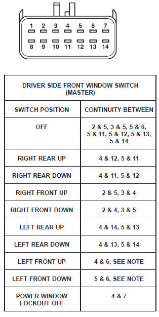 Fig. 1 Power Window Switch Continuity - Driver Side Front
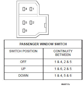 Fig. 2 Power Window Switch Continuity - Passenger Doors
Power window motor
Dodge Durango (DN) 1998-2003 Service Manual
- Lubrication and Maintenance
- Suspension
- Differential and Driveline
- Brakes
- Cooling System
- Battery
- Starting Systems
- Charging System
- Ignition System
- Instrument Panel Systems
- Audio Systems
- Horn Systems
- Speed Control System
- Turn Signal and Hazard Warning Systems
- Wiper and Washer Systems
- Lamps
- Passive Restraint Systems
- Electrically Heated Systems
- Power Distribution System
- Power Lock Systems
- Vehicle Theft/Security Systems
- Power Seat System
- Power Window Systems
- Power Mirror Systems
- Chime/Buzzer Warning Systems
- Overhead Console Systems
- Engine
- Exhaust System
- Frame and Bumpers
- Fuel System
- Steering
- Transmission and Transfer Case
- Tires and Wheels
- Body
- Heating and Air Conditioning
- Emission Control Systems
- Introduction
Categories
