Description and operation
DESCRIPTION A propeller shaft (Fig. 2), (Fig. 3), and (Fig. 4) is
the shaft which connects the transmission/transfer
case to the axle differential. This is the link through
which the engine power is transmitted to the axle.
The propeller shaft is designed and built with the
yoke lugs in line with each other which is called zero
phasing. This design produces the smoothest running
condition, an out-of-phase shaft can cause a vibration.
Tubular propeller shafts are balanced by the manufacturer
with weights spot welded to the tube. PRECAUTIONS Use the exact replacement parts when installing
the propeller shafts. The use of the correct replacement
parts helps to ensure safe operation. All fasteners
must be torqued to the specified values for safe
operation.
Also make alignment reference marks (Fig. 1) on
the propeller shaft yoke and axle, or transmission,
yoke prior to servicing. This helps to eliminate possible
vibration. CAUTION: Do not allow the propeller shaft to drop
or hang from any propeller shaft joint during
removal. Attach the propeller shaft to the vehicle
underside with wire to prevent damage to the joints.
1 - REFERENCE MARKS OPERATION The propeller shaft must operate through constantly
changing relative angles between the transmission
and axle. It must also be capable of changing
length while transmitting torque. The axle rides suspended
by springs in a floating motion. The propeller
shaft must be able to change operating angles when
going over various road surfaces. This is accomplished
through universal joints, which permit the
propeller shaft to operate at different angles. The slip
joints (or yokes) permit contraction or expansion (Fig.
2), (Fig. 3), and (Fig. 4).
Before undercoating a vehicle, the propeller
shaft and the U-joints should be covered to prevent
an out-of-balance condition and driveline
vibration. CAUTION: Use original equipment replacement
parts for attaching the propeller shafts. The specified
torque must always be applied when tightening
the fasteners. DESCRIPTION Vehicles equipped with a two-piece propeller shaft
uses a rubber insulated center bearing. The bearing
is used to support the shafts where they are joined
together.
1 - REAR AXLE 2 - COMPANION FLANGE 3 - TRANSFER CASE 4 - FRONT PROPELLER SHAFT 5 - COMPANION YOKE 6 - FRONT AXLE 7 - COMPANION FLANGE 8 - REAR PROPELLER SHAFT 9 - COMPANION YOKE OPERATION The propeller shaft center bearing serves to divide
the required propeller shaft length into two smaller
shafts, which has several inherent advantages. Having
two short propeller shafts instead of one long
shaft decreases the chance of unwanted noise and
vibrations. The shorter shafts are easier to balance
and serve to increase ground clearance while maintaining
acceptable driveline angles.
1 - REAR AXLE 2 - REAR PROPELLER SHAFT 3 - TRANSMISSION EXTENSION HOUSING 4 - CENTER BEARING
1 - REAR AXLE 2 - REAR PROPELLER SHAFT 3 - TRANSMISSION EXTENSION HOUSING DESCRIPTION Two different types of propeller shaft joints are
used in AN vehicles (Fig. 5) and (Fig. 6). None of the
joints are serviceable. If worn or damaged, they must
be replaced as a complete assembly.
1 - CROSS 2 - SEAL 3 - CAP AND NEEDLE BEARINGS LUBRICATION The factory installed universal joints are lubricated
for the life of the vehicle and do not need lubrication.
All universal joints should be inspected for leakage
and damage each time the vehicle is serviced. If seal
leakage or damage exists, the universal joint should
be replaced. DESCRIPTION When two shafts come together at a common joint,
the bend that is formed is called the operating angle.
The larger the angle, the larger the amount of angular
acceleration and deceleration of the joint. This
speeding up and slowing down of the joint must be
cancelled to produce a smooth power flow. OPERATION This cancellation is done through the phasing of a
propeller shaft and ensuring that the proper propeller
shaft joint working angles are maintained.
A propeller shaft is properly phased when the yoke
ends are in the same plane, or in line. A twisted
shaft will make the yokes out of phase and cause a
noticeable vibration.
When taking propeller shaft joint angle measurements,
or checking the phasing, of two piece shafts,
consider each shaft separately.
Ideally the driveline system should have; Propeller shaft speed (rpm) is the main factor in
determining the maximum allowable operating angle.
As a guide to the maximum normal operating angles
refer to (Fig. 7). Propeller shaft
 Fig. 1 Reference Marks on Yokes
Center bearing
 Fig. 2 Front Propeller Shaft
 Fig. 3 Rear Propeller Shaft with Center Bearing
 Fig. 4 Rear Propeller Shaft
Propeller shaft joints
 Fig. 5 Single Cardan U-Joint
Propeller shaft joint angle
 Fig. 6 Double Cardan U-Joint
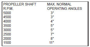 Fig. 7 Maximum Angles And Propeller Shaft Speed
Dodge Durango (DN) 1998-2003 Service Manual
- Lubrication and Maintenance
- Suspension
- Differential and Driveline
- Brakes
- Cooling System
- Battery
- Starting Systems
- Charging System
- Ignition System
- Instrument Panel Systems
- Audio Systems
- Horn Systems
- Speed Control System
- Turn Signal and Hazard Warning Systems
- Wiper and Washer Systems
- Lamps
- Passive Restraint Systems
- Electrically Heated Systems
- Power Distribution System
- Power Lock Systems
- Vehicle Theft/Security Systems
- Power Seat System
- Power Window Systems
- Power Mirror Systems
- Chime/Buzzer Warning Systems
- Overhead Console Systems
- Engine
- Exhaust System
- Frame and Bumpers
- Fuel System
- Steering
- Transmission and Transfer Case
- Tires and Wheels
- Body
- Heating and Air Conditioning
- Emission Control Systems
- Introduction
Categories
