Cylinder head cover
REMOVAL
LEFT SIDE COVER
(1) Disconnect negative cable from battery.
(2) Remove the resonator assemble and air inlet hose.
(3) Disconnect injector connectors and un-clip the injector harness.
(4) Route injector harness in front of cylinder head cover.
(5) Disconnect the left side breather tube and remove the breather tube.
(6) Remove the cylinder head cover mounting bolts.
(7) Remove cylinder head cover and gasket.
NOTE: The gasket may be used again, provided no cuts, tears, or deformation has occurred.
INSTALLATION
CAUTION: Do not use harsh cleaners to clean the cylinder head covers. Severe damage to covers may occur. CAUTION: DO NOT allow other components including the wire harness to rest on or against the cylinder head cover. Prolonged contact with other objects may wear a hole in the engine cylinder head cover.
(1) Clean cylinder head cover and both sealing surfaces.
Inspect and replace gasket as necessary.
(2) Install cylinder head cover and hand start all fasteners. Verify that all studs are in the correct location shown in (Fig. 54).
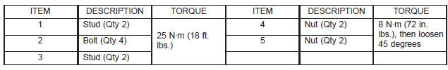
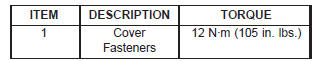
(3) Tighten cylinder head cover bolts and double ended studs to 12 N*m (105 in. lbs.).
(4) Install left side breather and connect breather tube.
(5) Connect injector electrical connectors and injector harness retaining clips.
(6) Install the resonator and air inlet hose.
(7) Connect negative cable to battery.
REMOVAL
RIGHT SIDE COVER
(1) Disconnect battery negative cable.
(2) Remove air cleaner assembly, resonator assembly and air inlet hose.
(3) Drain cooling system, below the level of the heater hoses. Refer to COOLING SYSTEM.
(4) Remove accessory drive belt.
(5) Remove air conditioning compressor retaining bolts and move compressor to the left.
(6) Remove heater hoses.
(7) Disconnect injector and ignition coil connectors.
(8) Disconnect and remove positive crankcase ventilation (PCV) hose.
(9) Remove oil fill tube.
(10) Un-clip injector and ignition coil harness and move away from cylinder head cover.
(11) Remove right rear breather tube and filter assembly.
 Fig. 53 Exhaust Manifold-Left
(12) Remove cylinder head cover retaining bolts.
(13) Remove cylinder head cover.
NOTE: The gasket may be used again, provided no cuts, tears, or deformation has occurred.
INSTALLATION
CAUTION: Do not use harsh cleaners to clean the cylinder head covers. Severe damage to covers may occur.
 Fig. 54 Cylinder Head Cover-Left
 CAUTION: DO NOT allow other
components including
the wire harness to rest on or against the
engine cylinder head cover. Prolonged contact with
other objects may wear a hole in the cylinder head
cover.
CAUTION: DO NOT allow other
components including
the wire harness to rest on or against the
engine cylinder head cover. Prolonged contact with
other objects may wear a hole in the cylinder head
cover.
(1) Clean cylinder head cover and both sealing surfaces.
Inspect and replace gasket as necessary.
(2) Install cylinder head cover and hand start all fasteners. Verify that all double ended studs are in the correct location shown in (Fig. 55).
 Fig. 55 Cylinder Head Cover-Right
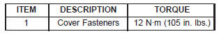 (3) Tighten cylinder head cover
bolts and double
ended studs to 12 N*m (105 in. lbs).
(3) Tighten cylinder head cover
bolts and double
ended studs to 12 N*m (105 in. lbs).
(4) Install right rear breather tube and filter assembly.
(5) Connect injector, ignition coil electrical connectors and harness retaining clips.
(6) Install the oil fill tube.
(7) Install PCV hose.
(8) Install heater hoses.
(9) Install air conditioning compressor retaining bolts.
(10) Install accessory drive belt (11) Fill Cooling system (12) Install air cleaner assembly, resonator assembly and air inlet hose.
(13) Connect battery negative cable.
Dodge Durango (DN) 1998-2003 Service Manual
- Lubrication and Maintenance
- Suspension
- Differential and Driveline
- Brakes
- Cooling System
- Battery
- Starting Systems
- Charging System
- Ignition System
- Instrument Panel Systems
- Audio Systems
- Horn Systems
- Speed Control System
- Turn Signal and Hazard Warning Systems
- Wiper and Washer Systems
- Lamps
- Passive Restraint Systems
- Electrically Heated Systems
- Power Distribution System
- Power Lock Systems
- Vehicle Theft/Security Systems
- Power Seat System
- Power Window Systems
- Power Mirror Systems
- Chime/Buzzer Warning Systems
- Overhead Console Systems
- Engine
- Exhaust System
- Frame and Bumpers
- Fuel System
- Steering
- Transmission and Transfer Case
- Tires and Wheels
- Body
- Heating and Air Conditioning
- Emission Control Systems
- Introduction
Categories
