Crankshaft main bearings. Oil pan 4x2 vehicle
CRANKSHAFT MAIN BEARING SELECTION The main bearings are "select fit" to achieve proper
oil clearances. For main bearing selection, the crankshaft
position sensor target wheel has grade identification
marks stamped into it (Fig. 104). These marks
are read from left to right, corresponding with journal
number 1, 2, 3, 4 and 5. The crankshaft position
sensor target wheel is mounted to the number 8
counter weight on the crankshaft.
NOTE: Service main bearings color coded. These
color codes identify what size (grade) the bearing
is. CHECKING CRANKSHAFT END PLAY (1) Mount a dial indicator to a stationary point at
front of engine. Locate the probe perpendicular
against nose of crankshaft (Fig. 105).
(2) Move the crankshaft all the way to the rear of
it's travel.
(3) Zero the dial indicator.
(4) Move the crankshaft all the way to the front of
it's travel and read the dial indicator. Refer to Crankshaft
End Play Specification Chart. REMOVAL (1) Drain the cooling system. Refer to COOLING
SYSTEM.
(2) Remove the upper fan shroud. Refer to procedure
in this section.
(3) Remove the throttle body resonator and air
inlet hose.
(4) Remove the intake manifold. Refer to procedure
in this section.
(5) Raise vehicle on hoist.
(6) Disconnect exhaust pipe at exhaust manifolds.
Refer to EXHAUST SYSTEM.
(7) Remove the structural dust cover (Fig. 106).
Refer to procedure in this section.
(8) Drain engine oil and remove oil filter.
(9) Position suitable jack under engine.
1 - LEFT CYLINDER HEAD 2 - RIGHT CYLINDER HEAD
1 - ADJUSTABLE PLIERS 2 - CAMSHAFT DOWEL (10) Remove both left and right side engine mount
through bolts (Fig. 107).
1 - TORQUE WRENCH 2 - SPECIAL TOOL 6958 WITH ADAPTER PINS 8346 3 - LEFT CAMSHAFT SPROCKET 4 - RIGHT CAMSHAFT SPROCKET (11) Raise engine to provide clearance to remove
oil pan.
1 - REARMOST CRANKSHAFT COUNTER WEIGHT 2 - TARGET WHEEL 3 - MAIN BEARING SELECT FIT MARKINGS MAIN BEARING SELECTION CHART-4.7L
(12) Place blocks of wood between engine brackets
and lower mounts to provide stability to engine.
NOTE: Do not pry on oil pan or oil pan gasket.
Gasket is mounted to engine and does not come
out with oil pan.
(13) Remove the oil pan mounting bolts and oil
pan (Fig. 108).
(14) Unbolt oil pump pickup tube and remove tube
and oil pan gasket from engine. CRANKSHAFT END PLAY SPECIFICATION CHART
INSTALLATION (1) Clean the oil pan gasket mating surface of the
bedplate and oil pan.
(2) Position the oil pan gasket and pickup tube
with new o-ring. Install the mounting bolt and nuts.
Tighten bolt and nuts to 28 N*m (20 ft. lbs.).
(3) Position the oil pan and install the mounting
bolts. Tighten the mounting bolts to 15 N*m (11 ft.
lbs.) in the sequence shown (Fig. 108).
(4) Raise the engine and remove the blocks of
wood.
1 - LOCKNUT AND WASHER 2 - ENGINE MOUNT/INSULATOR 3 - THROUGH BOLT 4 - FRAME
(5) Lower engine and install both the left and
right side engine mount through bolts (Fig. 107).
Tighten the nuts to 68 N*m (50 ft. lbs.).
(6) Remove jack and install oil filter.
(7) Install structural dust cover.
(8) Install exhaust pipe onto exhaust manifolds.
(9) Lower vehicle.
(10) Install intake manifold.
(11) Install throttle body resonator and air inlet
hose.
(12) Install upper fan shroud.
(13) Fill cooling system.
(14) Fill engine oil.
(15) Start engine and check for leaks.Crankshaft main bearings
Oil pan 4x2 vehicle
 Fig. 101 Timing Chain to Sprocket Alignment
 Fig. 102 Camshaft Sprocket Installation
 Fig. 103 Tightening Right Side Cam Sprocket Retaining Bolt
 Fig. 104 Main Bearing Markings on Target Wheel
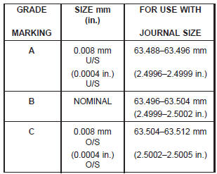
 Fig. 105 Checking Crankshaft End Play-Typical
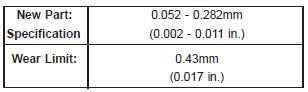
 Fig. 106 Structural Dust Cover Removal / Installation
 Fig. 107 Engine Mount Through Bolt and Nut Removal / Installation
 Fig. 108 Oil Pan Mounting Bolts and Oil Pan
Dodge Durango (DN) 1998-2003 Service Manual
- Lubrication and Maintenance
- Suspension
- Differential and Driveline
- Brakes
- Cooling System
- Battery
- Starting Systems
- Charging System
- Ignition System
- Instrument Panel Systems
- Audio Systems
- Horn Systems
- Speed Control System
- Turn Signal and Hazard Warning Systems
- Wiper and Washer Systems
- Lamps
- Passive Restraint Systems
- Electrically Heated Systems
- Power Distribution System
- Power Lock Systems
- Vehicle Theft/Security Systems
- Power Seat System
- Power Window Systems
- Power Mirror Systems
- Chime/Buzzer Warning Systems
- Overhead Console Systems
- Engine
- Exhaust System
- Frame and Bumpers
- Fuel System
- Steering
- Transmission and Transfer Case
- Tires and Wheels
- Body
- Heating and Air Conditioning
- Emission Control Systems
- Introduction
Categories
