Brake lamp switch. Red brake warning lamp
The brake lamp switch can be tested with an ohmmeter.
The ohmmeter is used to check continuity
between the pin terminals (Fig. 4). SWITCH CIRCUIT IDENTIFICATION
1 - TERMINAL PINS 2 - PLUNGER TEST POSITIONS SWITCH CONTINUITY TEST NOTE: Disconnect switch harness before testing
switch continuity. With switch plunger extended, attach test leads to
pins 1 and 2. Replace switch if meter indicates no
continuity.
With switch plunger retracted, attach test leads to
pins 3 and 4. Replace switch if meter indicates no
continuity.
With switch plunger retracted, attach test leads to
pins 5 and 6. Replace switch if meter indicates no
continuity. The red warning lamp is in circuit with the parking
brake switch and pressure differential switch in
the combination valve.
The red lamp illuminates when the parking brakes
are applied, or when a pressure drop occurs in the
front or rear brake hydraulic circuit. The lamp illuminates for approximately 2-4 seconds
at every engine start up. This is a self test feature
designed to check bulb and circuit operation.
A pressure drop in the front or rear brake hydraulic
circuit activates the pressure differential valve
inside the combination valve. A pressure decrease
moves the valve toward the low pressure side. As the
valve moves, it pushes the pressure differential
switch contact plunger upward. This closes the
switch internal contacts and completes the circuit to
the red warning lamp. The lamp will remain on until
repairs are made and normal fluid pressure restored.Brake lamp switch
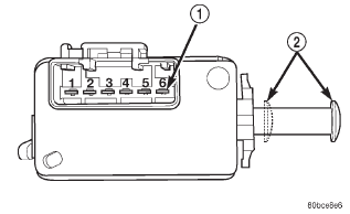 Fig. 4 Brake Lamp Switch Terminal Identification
Red brake warning lamp
Dodge Durango (DN) 1998-2003 Service Manual
- Lubrication and Maintenance
- Suspension
- Differential and Driveline
- Brakes
- Cooling System
- Battery
- Starting Systems
- Charging System
- Ignition System
- Instrument Panel Systems
- Audio Systems
- Horn Systems
- Speed Control System
- Turn Signal and Hazard Warning Systems
- Wiper and Washer Systems
- Lamps
- Passive Restraint Systems
- Electrically Heated Systems
- Power Distribution System
- Power Lock Systems
- Vehicle Theft/Security Systems
- Power Seat System
- Power Window Systems
- Power Mirror Systems
- Chime/Buzzer Warning Systems
- Overhead Console Systems
- Engine
- Exhaust System
- Frame and Bumpers
- Fuel System
- Steering
- Transmission and Transfer Case
- Tires and Wheels
- Body
- Heating and Air Conditioning
- Emission Control Systems
- Introduction
Categories
