Blower motor relay. Blower motor resistor
REMOVAL The blower motor relay (Voltage Reduction Relay
or VRR) is mounted with a single screw directly to
the instrument panel's structural plastic inside the
glove box opening, next to the left-side energy-absorbing
bracket (Fig. 20).
(1) Disconnect and isolate the battery negative
cable.
(2) Roll down the glove box as described in the
Glove Box section of Instrument Panel Systems. (3) Using a short or 90 degree screwdriver, remove
the screw that secures the blower motor relay (VRR)
to the steel clip in the instrument panel plastic
flange.
(4) Maneuver the VRR into the glove box opening
far enough for access, and disengage the wiring harness
from the relay.
(5) Remove the relay through the glove box opening. INSTALLATION (1) Position the relay into the instrument panel
inside the glove box opening.
(2) Align the VRR with the connector and engage
the wiring harness to the relay.
(3) Align the relay with the steel clip in the instrument
panel, and insert and tighten the single screw
to 2.2 N*m (20 in. lbs.).
(4) Roll up the glove box as described in the Glove
Box Installation section of Instrument Panel Systems.
(5) Reconnect the battery negative cable.
1 - BLOWER MOTOR RESISTOR CONNECTOR 2 - BLOWER MOTOR RELAY 3 - BLOWER MOTOR CONNECTOR 4 - GLOVE BOX LAMP CONNECTOR FRONT REMOVAL (1) Disconnect and isolate the battery negative
cable.
(2) Remove the cowl plenum cover/grille panel
from the cowl top. See Vacuum Reservoir in the
Removal and Installation section of this group for the
procedures.
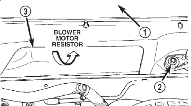
(3) Reach through the cowl plenum access hole
(Fig. 21) to remove the two hex screws that secure the front blower motor
resistor to the cowl plenum
panel.
1 - WINDSHIELD 2 - RIGHT WIPER PIVOT 3 - COWL PLENUM ACCESS HOLE (4) Pull the front blower motor resistor and its
wire harness out of the plenum panel and through
the cowl plenum access hole far enough to access the
wire harness connector.
(5) Unplug the front blower motor resistor from
the wire harness connector.
(6) Remove the front blower motor resistor from
the cowl plenum. INSTALLATION (1) Plug the front blower motor resistor into the
wire harness connector.
(2) Install the front blower motor resistor to the
cowl plenum panel by feeding the resistor and wire
harness back through the cowl plenum access hole.
(3) Install and tighten the two screws that secure
the front blower motor resistor to the cowl plenum
panel. Tighten the mounting screws to 2.2 N*m (20
in. lbs.).
(4) Reinstall the cowl plenum cover/grille panel to
the cowl top. See Vacuum Reservoir in the Removal
and Installation section of this group for the procedures.
(5) Connect the battery negative cable. REAR The rear blower motor resistor is used only on
models with the optional rear overhead A/C unit. REMOVAL (1) Disconnect and isolate the battery negative
cable.
(2) Remove the headliner from the passenger compartment
of the vehicle. Refer to Group 23 - Body for
the procedures. (3) Disconnect the B-pillar drain hoses from the
wye fittings on each side of the rear overhead A/C
unit (Fig. 22).
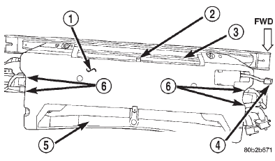
1 - REAR OVERHEAD A/C UNIT 2 - WYE FITTING 3 - CLIP 4 - GROMMET 5 - DRAIN HOSE (4) Remove the nine screws that secure the lower
housing cover to the rear overhead A/C unit.
(5) Release the lower housing cover snap retainer
near the center of the outlet side (rear) of the rear
overhead A/C unit (Fig. 23).
1 - REAR OVERHEAD A/C UNIT LOWER HOUSING COVER 2 - SNAP RETAINER 3 - OUTLET SIDE 4 - BLOWER MOTOR SWITCH WIRE HARNESS CONNECTOR 5 - INLET SIDE 6 - DRAIN HOSES (6) Feed the rear blower motor switch wire harness
and connector through the hole in the right end
of the rear overhead A/C unit lower housing cover
while removing the cover from the unit.
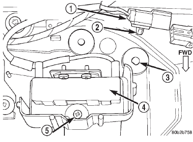
(7) Disengage the rear blower motor resistor wire
harness connector retainer from the mounting hole in
the right rear corner of the rear overhead A/C unit
upper housing cover (Fig. 24).
1 - WIRE HARNESS CONNECTOR 2 - RETAINER 3 - MOUNTING HOLE 4 - RESISTOR 5 - SCREW (8) Unplug the rear blower motor resistor wire
harness connector.
(9) Remove the screw that secures the rear blower
motor resistor bracket to the rear overhead A/C unit
upper housing cover.
(10) Remove the rear blower motor resistor and
bracket as a unit from the rear overhead A/C unit. INSTALLATION (1) Position the rear blower motor resistor and
bracket in the right rear corner of the rear overhead
A/C unit upper housing cover and secure it with the
mounting screw. Tighten the mounting screw to 2.2
N*m (20 in. lbs.).
(2) Plug in the rear blower motor resistor wire
harness connector.
(3) Engage the rear blower motor resistor wire
harness connector retainer to the mounting hole in
the right rear corner of the rear overhead A/C unit
upper housing cover.
(4) Feed the rear blower motor switch wire harness
and connector through the hole in the right end
of the rear overhead A/C unit lower housing cover
while positioning the cover to the unit. (5) Be certain that the lower housing cover snap
retainer near the center of the outlet side (rear) of
the rear overhead A/C unit is engaged.
(6) Install the nine screws that secure the lower
housing cover to the rear overhead A/C unit. Tighten
the mounting screws to 2.2 N*m (20 in. lbs.).
(7) Connect the B-pillar drain hoses to the wye fittings
on each side of the rear overhead A/C unit.
(8) Reinstall the headliner to the passenger compartment
of the vehicle. Refer to Group 23 - Body for
the procedures.
(9) Connect the battery negative cable.Blower motor relay
 Fig. 20 Blower Motor Relay (VRR) Location
Blower motor resistor
 Fig. 21 Blower Motor Resistor Remove/Install
 Fig. 22 Rear Overhead A/C Drain Hose Remove/ Install
 Fig. 23 Rear Overhead A/C Unit Lower Housing Cover Remove/Install
 Fig. 24 Rear Blower Motor Resistor Remove/Install
Dodge Durango (DN) 1998-2003 Service Manual
- Lubrication and Maintenance
- Suspension
- Differential and Driveline
- Brakes
- Cooling System
- Battery
- Starting Systems
- Charging System
- Ignition System
- Instrument Panel Systems
- Audio Systems
- Horn Systems
- Speed Control System
- Turn Signal and Hazard Warning Systems
- Wiper and Washer Systems
- Lamps
- Passive Restraint Systems
- Electrically Heated Systems
- Power Distribution System
- Power Lock Systems
- Vehicle Theft/Security Systems
- Power Seat System
- Power Window Systems
- Power Mirror Systems
- Chime/Buzzer Warning Systems
- Overhead Console Systems
- Engine
- Exhaust System
- Frame and Bumpers
- Fuel System
- Steering
- Transmission and Transfer Case
- Tires and Wheels
- Body
- Heating and Air Conditioning
- Emission Control Systems
- Introduction
