Blower motor. Blower motor relay
FRONT DESCRIPTION The blower motor and blower wheel are located in
the passenger side end of the heater-A/C housing,
below the glove box. The blower motor controls the
velocity of air flowing through the heater-A/C housing
by spinning a squirrel cage-type blower wheel
within the housing at the selected speed. The blower
motor and blower wheel can only be serviced with
the heater-A/C housing removed from the passenger
compartment. OPERATION The blower motor will only operate when the ignition
switch is in the On position, and the heater-A/C
mode control switch knob is in any position, except
Off. The blower motor receives a fused battery feed
through the blower motor relay (Voltage Reduction
Relay or VRR) whenever the ignition switch is in the
On position.
The blower motor battery feed circuit is protected
by a fuse in the Power Distribution Center (PDC).
The blower motor relay control circuit is protected by
a fuse in the junction block. Blower motor speed is
controlled by regulating the ground path through the
heater-A/C mode control switch, the blower motor
switch, the blower motor resistor, the blower motor
relay (VRR), and the high speed blower motor relay.
The blower motor and blower motor wheel cannot
be repaired and, if faulty or damaged, they must be
replaced. The blower motor and blower wheel are
each serviced separately. REAR DESCRIPTION The rear blower motor and blower wheel are
mounted to a blower wheel housing located inside the
rear overhead A/C unit, above the headliner. The
blower motor controls the velocity of air flowing
through the overhead A/C unit by spinning a wide
squirrel cage-type blower wheel within the housing
at the selected speed. Rear blower motor speed is
controlled by regulating the ground path through the
rear blower motor switch and the rear blower motor
resistor. OPERATION The rear blower motor will only operate when the
ignition switch is in the On position. The rear blower
motor receives a fused battery feed through a fuse in
the relay and fuse block whenever the ignition switch
is in the On position. The relay and fuse block is
attached to the back of the junction block, under the
left side of the instrument panel in the passenger
compartment.
The rear blower motor, blower wheel, and blower
wheel housing cannot be repaired and, if faulty or
damaged, they must be replaced as a complete factory-
balanced unit. DESCRIPTION The blower motor relay (also referred to as Voltage
Reduction Relay or VRR) is an International Standards
Organization (ISO)-type relay. The relay is an
electromechanical device that switches battery current
from a fuse in the Power Distribution Center
(PDC) directly to the blower motor. The relay is energized
when the relay coil is provided a voltage signal
by the ignition switch. This arrangement reduces the
amount of battery current that must flow through
the ignition switch. OPERATION The blower motor relay control circuit is protected
by a fuse located in the junction block. When the
relay is de-energized, the blower motor receives no
battery current. The VRR is used to reduce blower
speeds in Heat mode. In non-A/C modes, the relay is
de-energized and switches the current flow through
an added resistance in the resistor block. When an
A/C mode is selected, the relay is energized and the
normally open contact is used to bypass the added
resistor. The fuse is located in the small relay fuse
block that is attached to the Junction Block. The
relay is energized by grounding the coil low side with
the HVAC switch in any A/C mode. See Blower Motor
Relay in the Diagnosis and Testing section of this
group for more information.
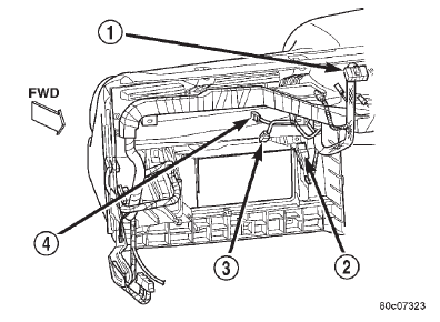
The blower motor relay is mounted with a single
screw directly to the instrument panel's structural plastic inside the glove box
opening, next to the leftside
energy-absorbing bracket (Fig. 1). Refer to the
PDC label for blower motor relay identification and
location.
The blower motor relay (VRR) cannot be repaired
and, if faulty or damaged, it must be replaced.
1 - BLOWER MOTOR RESISTOR CONNECTOR 2 - BLOWER MOTOR RELAY 3 - BLOWER MOTOR CONNECTOR 4 - GLOVE BOX LAMP CONNECTORBlower motor
Blower motor relay
 Fig. 1 Blower Motor Relay (VRR) Location
Dodge Durango (DN) 1998-2003 Service Manual
- Lubrication and Maintenance
- Suspension
- Differential and Driveline
- Brakes
- Cooling System
- Battery
- Starting Systems
- Charging System
- Ignition System
- Instrument Panel Systems
- Audio Systems
- Horn Systems
- Speed Control System
- Turn Signal and Hazard Warning Systems
- Wiper and Washer Systems
- Lamps
- Passive Restraint Systems
- Electrically Heated Systems
- Power Distribution System
- Power Lock Systems
- Vehicle Theft/Security Systems
- Power Seat System
- Power Window Systems
- Power Mirror Systems
- Chime/Buzzer Warning Systems
- Overhead Console Systems
- Engine
- Exhaust System
- Frame and Bumpers
- Fuel System
- Steering
- Transmission and Transfer Case
- Tires and Wheels
- Body
- Heating and Air Conditioning
- Emission Control Systems
- Introduction
