Structural cover. Engine assembly
REMOVAL (1) Raise vehicle on hoist.
(2) Remove the left hand exhaust pipe from
exhaust manifold. Refer to Group 11, Exhaust System.
(3) Loosen the right hand exhaust manifold-to-exhaust
pipe retaining bolts.
(4) Remove the eight bolts retaining structural
cover (Fig. 39).
(5) Pivot the exhaust pipe downward and remove
the structural cover. INSTALLATION CAUTION: The structural cover must be installed
as described in the following steps. Failure to do so
will cause severe damage to the cover. (1) Position the structural cover in the vehicle.
(2) Install all four bolts retaining the cover-to-engine.
DO NOT tighten the bolts at this time.
(3) Install the four cover-to-transmission bolts. Do
NOT tighten at this time. CAUTION: The structural cover must be held tightly
against both the engine and the transmission bell
housing during tightening sequence. Failure to do
so may cause damage to the cover. (4) Starting with the two rear cover-to-engine
bolts, tighten bolts (1) (Fig. 39) to 54 N*m (40 ft. lbs.),
then tighten bolts (2) (Fig. 39) and (3) to 54 N*m ( 40
ft. lbs.) in the sequence shown.
(5) Install the exhaust pipe on left hand exhaust
manifold.
(6) Tighten exhaust manifold-to-exhaust pipe
retaining bolts to 20-26 N*m (15-20 ft. lbs.). REMOVAL NOTE: This procedure applies to both the 4X2 and
4X4 vehicles, steps that apply to the 4X4 vehicle
only, are identified. (1) Disconnect the battery negative and positive
cables.
(2) Remove the battery and the battery tray. Refer
to BATTERY.
(3) Raise vehicle on hoist.
(4) Remove exhaust crossover pipe from exhaust
manifolds. Refer to EXHAUST SYSTEM.
(5) 4X4 vehicles Disconnect axle vent tube from
left side engine mount.
(6) Remove the through bolt retaining nut and bolt
from both the left and right side engine mounts (Fig.
40) (Fig. 41).
(7) 4X4 vehicles Remove locknut from left and
right side engine mount brackets (Fig. 41).
(8) Disconnect two ground straps from the lower
left hand side and one ground strap from the lower
right hand side of the engine.
(9) Disconnect crankshaft position sensor. (Fig. 43) NOTE: The following step applies to 4X4 vehicles
equipped with automatic transmission only. (10) 4X4 vehicles Remove the axle isolator
bracket from the engine, transmission and the axle
(Fig. 42).
(11) Remove structural cover. Refer to Structural
Cover in this section for procedure.
(12) Remove starter. Refer to STARTING SYSTEM.
(13) Drain cooling system. Refer to COOLING
SYSTEM.
(14) Remove torque converter bolts (Automatic
Transmission Only). Refer to TRANSMISSION.
(15) Remove transmission to engine mounting
bolts.
(16) Disconnect the engine block heater power
cable from the block heater, if equipped.
1 - LOCKNUT AND WASHER 2 - ENGINE MOUNT/INSULATOR 3 - THROUGH BOLT 4 - FRAME (17) Lower vehicle.
(18) Remove throttle body resonator assembly and
air inlet hose.
(19) Disconnect throttle and speed control cables.
(20) Disconnect tube from both the left and right
side crankcase breathers (Fig. 44). Remove breathers
(21) Discharge A/C system. Refer to HEATING and
AIR CONDITIONING.
(22) Remove A/C compressor.
(23) Remove shroud, fan assemblies and accessory
drive belt. Refer to COOLING SYSTEM.
(24) Disconnect transmission oil cooler lines at the
radiator.
(25) Disconnect radiator upper and lower hoses.
Refer to COOLING SYSTEM.
(26) Remove radiator, A/C condenser and transmission
oil cooler as an assembly. Refer to COOLING
SYSTEM.
(27) Remove generator.
(28) Disconnect the two heater hoses from the timing
chain cover and heater core.
(29) Unclip and remove heater hoses and tubes
from the intake manifold (Fig. 45).
(30) Disconnect engine harness at the following
points :
1 - ENGINE MOUNT BRACKET (2) 2 - THROUGH BOLT (2) 3 - LOCKNUT AND WASHER (2) 4 - ENGINE ISOLATOR TO ENGINE MOUNT BRACKET STUD (2) 5 - LOCKNUT (2) (31) Disconnect the vacuum lines at the throttle
body and intake manifold.
(32) Release fuel rail pressure then disconnect the
fuel supply quick connect fitting at the fuel rail.
Refer toFUEL SYSTEM for procedure.
(33) Remove power steering pump and position out
of the way.
(34) Install Special Tools 8400 Lifting Studs, into
the cylinder heads.
(35) Install Engine Lifting Fixture Special Tool
8347 (Fig. 47) following these steps.
1 - TRANSMISSION 2 - AXLE ISOLATOR BRACKET 3 - FRONT AXLE 4X4 VEHICLES 4 - BOLTS 5 - ENGINE (36) Disconnect body ground strap at the right side
cowl (Fig. 48).
(37) Disconnect body ground strap at the left side
cowl (Fig. 49). NOTE: It will be necessary to support the transmission
in order to remove the engine. (38) Position a suitable jack under the transmission.
(39) Remove engine from the vehicle. INSTALLATION (1) Position engine in the vehicle.
Position both the left and right side engine mount
brackets and install the through bolts and nuts.
Tighten nuts to 4X2 vehicles 95 N*m (70 ft. lbs.).
4X4 vehicles 102 N*m (75 ft. lbs.).
1 - CRANKSHAFT POSITION SENSOR 2 - CYLINDER HEAD COVER 3 - CAMSHAFT POSITION SENSOR 4 - RIGHT SIDE CYLINDER BLOCK
1 - CRANKCASE BREATHERS (2) 4X4 vehicles Install locknuts onto the engine
mount brackets. Tighten locknuts to 41 N*m (30 ft.
lbs.).
(3) Remove jack from under the transmission.
(4) Remove Engine Lifting Fixture Special Tool
8347 (Fig. 47).
(5) Remove Special Tools 8400 Lifting Studs.
(6) Position generator wiring behind the oil dipstick
tube, then install the oil dipstick tube upper
mounting bolt.
(7) Connect both left and right side body ground
straps.
1 - HEATER HOSES AND TUBES 2 - ROUTING/RETAINING CLIPS (8) Install power steering pump.
(9) Connect fuel supply line quick connect fitting.
(10) Connect the vacuum lines at the throttle body
and intake manifold.
(11) Connect engine harness at the following
points (Fig. 46) : (12) Position and install heater hoses and tubes
onto intake manifold.
(13) Install the heater hoses onto the heater core
and the engine front cover.
(14) Install generator.
(15) Install A/C condenser, radiator and transmission
oil cooler as an assembly.
(16) Connect radiator upper and lower hoses.
(17) Connect the transmission oil cooler lines to
the radiator.
(18) Install accessory drive belt, fan assembly and
shroud.
(19) Install A/C compressor. Tighten the A/C compressor
and generator M10 mounting bolts 40-68N*M
(30-50 ft. lbs.) and the M8 bolts 22-34 N*m (200-300
in. lbs.).
1 - THROTTLE BODY 2 - TPS 3 - IAC MOTOR 4 - IAT SENSOR 5 - MOUNTING SCREWS (20) Install both breathers. Connect tube to both
crankcase breathers (Fig. 44).
(21) Connect throttle and speed control cables.
(22) Install throttle body resonator assembly and
air inlet hose. Tighten clamps 4 N*m (35 in. lbs.).
(23) Raise vehicle.
(24) Install transmission to engine mounting bolts.
Tighten the bolts to 41 N*m (30 ft. lbs.).
(25) Install torque converter bolts (Automatic
Transmission Only).
(26) Connect crankshaft position sensor (Fig. 43).
(27) 4X4 vehicles Position and install the axle
isolator bracket onto the axle, transmission and
engine block. Tighten bolts to specification. Refer to
Specifications in this section.
(28) Install starter. CAUTION: The structural cover requires a specific
torque sequence. Failure to follow this sequence
may cause severe damage to the cover.
1 - ATTACHING LOCATION 2 - ADJUSTABLE HOOK 3 - SPECIAL TOOL 8347 ENGINE LIFT FIXTURE 4 - ATTACHING LOCATIONS (29) Install structural cover. Refer to Structural
Cover in this section.
(30) Install exhaust crossover pipe.
(31) Install engine block heater power cable, If
equipped.
(32) 4X4 vehicles Connect axle vent tube to left
side engine mount.
(33) Lower vehicle.
(34) Check and fill engine oil.
(35) Recharge the A/C system.
(36) Refill the engine cooling system. Refer to
COOLING SYSTEM.
(37) Install the battery tray and battery.
(38) Connect the battery positive and negative
cables.
(39) Start the engine and check for leaks.
1 - NUT 2 - A/C ACCUMULATOR 3 - GROUND STRAPStructural cover
 Fig. 39 Structural Cover
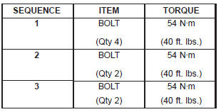
Engine assembly
 Fig. 40 Engine Mount Through Bolt and Nut Removal / Installation-4X2 Vehicles
 Fig. 41 Engine Mount Through Bolt and Nut Removal / Installation-4X4 Vehicles
 Fig. 42 Axle Isolator Bracket Removal / Installation-4X4 Vehicles With
Automatic Transmission
Fig. 42 Axle Isolator Bracket Removal / Installation-4X4 Vehicles With
Automatic Transmission
 Fig. 43 Crankshaft Position Sensor
 Fig. 44 Crankcase Breather Connection Points
 Fig. 45 Heater Hoses and Tubes Removal / Installation
 Fig. 46 Throttle Body Connection Points
 Fig. 47 Engine Lifting Fixture Attachment Locations
 Fig. 48 Body Ground Strap-Right Side Removal / Installation
Dodge Durango (DN) 1998-2003 Service Manual
- Lubrication and Maintenance
- Suspension
- Differential and Driveline
- Brakes
- Cooling System
- Battery
- Starting Systems
- Charging System
- Ignition System
- Instrument Panel Systems
- Audio Systems
- Horn Systems
- Speed Control System
- Turn Signal and Hazard Warning Systems
- Wiper and Washer Systems
- Lamps
- Passive Restraint Systems
- Electrically Heated Systems
- Power Distribution System
- Power Lock Systems
- Vehicle Theft/Security Systems
- Power Seat System
- Power Window Systems
- Power Mirror Systems
- Chime/Buzzer Warning Systems
- Overhead Console Systems
- Engine
- Exhaust System
- Frame and Bumpers
- Fuel System
- Steering
- Transmission and Transfer Case
- Tires and Wheels
- Body
- Heating and Air Conditioning
- Emission Control Systems
- Introduction
Categories
