Intake manifold
REMOVAL
(1) Disconnect negative cable from battery.
(2) Remove resonator assembly and air inlet hose.
(3) Disconnect throttle and speed control cables.
(4) Disconnect electrical connectors for the following components: Refer to FUEL SYSTEM for component locations.
- Manifold Absolute Pressure (MAP) Sensor
- Intake Air Temperature (IAT) Sensor
- Throttle Position (TPS) Sensor
- Coolant Temperature (CTS) Sensor
- Idle Air Control (IAC) Motor
(5) Disconnect vapor purge hose, brake booster hose, speed control servo hose, positive crankcase ventilation (PCV) hose.
(6) Disconnect generator electrical connections.
(7) Disconnect air conditioning compressor electrical connections.
(8) Disconnect left and right radio suppressor straps.
(9) Disconnect and remove ignition coil towers.
(10) Remove top oil dipstick tube retaining bolt and ground strap.
(11) Bleed fuel system. Refer to FUEL SYSTEM.
(12) Remove fuel rail.
(13) Remove throttle body assembly and mounting bracket.
(14) Drain cooling system below coolant temperature level. Refer to COOLING SYSTEM.
(15) Remove the heater hoses from the engine front cover and the heater core.
(16) Unclip and remove heater hoses and tubes from intake manifold (Fig. 50).
(17) Remove coolant temperature sensor. Refer to FUEL SYSTEM.
(18) Remove intake manifold retaining fasteners in reverse order of tightening sequence (Fig. 51).
(19) Remove intake manifold.
INSTALLATION
(1) Install intake manifold gaskets.
(2) Install intake manifold.
(3) Install intake manifold retaining bolts and tighten in sequence shown in (Fig. 51) to 12 N*m (105 in. lbs.).
(4) Install left and right radio suppressor straps.
(5) Install throttle body assembly.
(6) Install throttle cable bracket.
(7) Connect throttle cable and speed control cable to throttle body.
(8) Install fuel rail.
(9) Install ignition coil towers.
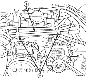 Fig. 50 Heater Hoses and Tubes Removal / Installation
1 - HEATER HOSES AND TUBES
2 - ROUTING/RETAINING CLIPS
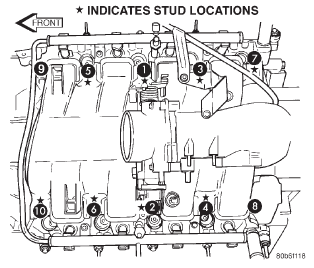 Fig. 51 Intake Manifold Tightening Sequence
(10) Position and install heater hoses and tubes onto intake manifold.
(11) Install the heater hoses to the heater core and engine front cover.
(12) Connect electrical connectors for the following components:
- Manifold Absolute Pressure (MAP) Sensor
- Intake Air Temperature (IAT) Sensor
- Throttle Position (TPS) Sensor
- Coolant Temperature (CTS) Sensor
- Idle Air Control (IAC) Motor
- Ignition coil towers
- Fuel injectors
(13) Install top oil dipstick tube retaining bolt and ground strap.
(14) Connect generator electrical connections.
(15) Connect Vapor purge hose, Brake booster hose, Speed control servo hose, Positive crankcase ventilation (PCV) hose.
(16) Fill cooling system.
(17) Install resonator assembly and air inlet hose.
(18) Connect negative cable to battery.
Dodge Durango (DN) 1998-2003 Service Manual
- Lubrication and Maintenance
- Suspension
- Differential and Driveline
- Brakes
- Cooling System
- Battery
- Starting Systems
- Charging System
- Ignition System
- Instrument Panel Systems
- Audio Systems
- Horn Systems
- Speed Control System
- Turn Signal and Hazard Warning Systems
- Wiper and Washer Systems
- Lamps
- Passive Restraint Systems
- Electrically Heated Systems
- Power Distribution System
- Power Lock Systems
- Vehicle Theft/Security Systems
- Power Seat System
- Power Window Systems
- Power Mirror Systems
- Chime/Buzzer Warning Systems
- Overhead Console Systems
- Engine
- Exhaust System
- Frame and Bumpers
- Fuel System
- Steering
- Transmission and Transfer Case
- Tires and Wheels
- Body
- Heating and Air Conditioning
- Emission Control Systems
- Introduction
Categories
