Heater-a/c control. Heater performance
Satisfactory heater and air conditioner performance
depends upon proper operation and adjustment
of all operating controls and refrigeration
system components. For circuit descriptions and diagrams,
refer to 8W-42 - Air Conditioning/Heater in
Group 8W - Wiring Diagrams. These inspections,
tests, and adjustments should be used to locate the
cause of a malfunction.
Operation must be tested as described in the following
sequence:
(1) Move the temperature control knob quickly to
the full hot and the full cold positions. There should
be a distinct sound of the blend-air door hitting its
stops within the heater-A/C housing at the end of knob travel in each
direction, with no spring-back of
the knob. If not OK, inspect the condition, routing,
installation and adjustment of the temperature control
cable. See Temperature Control Cable in the
Removal and Installation section and in the Adjustments
section of this group for more information.
(2) Inspect and adjust the serpentine drive belt.
Refer to Group 7 - Cooling System for the procedures.
(3) Start the engine and hold the idle speed at
1,300 rpm.
(4) On vehicles with air conditioning, turn the
temperature control knob to the extreme counterclockwise
(Cool) position, and set the mode control
switch knob in the Bi-Level (A/C) position. The outside
(recirculation) air door should be open to outside
air. If not OK, see Vacuum System in the Diagnosis
and Testing section of this group.
(5) Open the vehicle windows. Test the blower
motor operation in all speeds. If not OK, see Blower
Motor in the Diagnosis and Testing section of this
group. Leave the blower motor switch knob in the
highest speed position.
(6) On vehicles with air conditioning, the compressor
should be running and the air conditioning system
in operation unless the ambient air temperature
is below about -1 C (30 F). If not OK, see A/C Performance
in the Diagnosis and Testing section of this
group.
(7) Check the mode control switch operation. The
heater and air conditioner systems should respond as
described in the owner's manual in the vehicle glove
box to each mode selected. Reduce the engine speed
to normal idle. The vacuum will be high at low idle
and the vacuum actuators should respond quickly. If
not OK, see Vacuum System in the Diagnosis and
Testing section of this group.
(8) If the vacuum tests, and the electrical component
and circuit tests reveal no problems, disassemble
the heater-A/C housing to inspect for mechanical
misalignment or binding of the mode doors. Before performing the following tests, refer to
Group 7 - Cooling System for the procedures to check
the engine coolant level and flow, engine coolant
reserve/recovery system operation, accessory drive
belt condition and tension, radiator air flow and the
fan drive operation. Also be certain that the accessory
vacuum supply line is connected at the engine
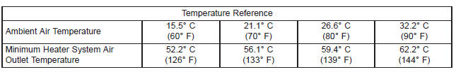
vacuum source. MAXIMUM HEATER OUTPUT Engine coolant is delivered to the heater core
through two heater hoses. With the engine idling at
normal operating temperature, set the temperature
control knob in the full hot position, the mode control
switch knob in the floor position, and the blower
motor switch knob in the highest speed position.
Using a test thermometer, check the temperature of
the air being discharged at the heater-A/C housing
floor outlets. Compare the test thermometer reading
to the Temperature Reference chart.
If the floor outlet air temperature is too low, refer
to Group 7 - Cooling System to check the engine coolant
temperature specifications. Both of the heater
hoses should be hot to the touch. The coolant return
heater hose should be slightly cooler than the coolant
supply heater hose. If the return hose is much cooler
than the supply hose, locate and repair the engine
coolant flow obstruction in the cooling system. Refer
to Group 7 - Cooling System for the procedures.
An alternate method of checking heater performance
is to use a DRB scan tool to monitor the
engine coolant temperature. The floor outlet air temperature
reading should be no more than 4.5 C (40
F) lower than the engine coolant temperature reading. OBSTRUCTED COOLANT FLOW If proper coolant flow through the cooling system is
verified, and heater outlet air temperature is still
low, a mechanical problem may exist. MECHANICAL PROBLEMS Possible locations or causes of insufficient heat: TEMPERATURE CONTROL If the heater outlet air temperature cannot be
adjusted with the temperature control knob on the
heater-A/C control panel, the following could require
service:
2. Air trapped in engine
cooling system.
3. Incorrect engine
coolant temperature.
4. Temperature control
cable improperly installed
or not adjusted.
5. Blend-air door not
operating properly.
6. Insufficient air flow
through heater housing.
7. Improper blower motor
operation.
2. Check the operation of the coolant reserve/recovery
system. Refer to Group 7 - Cooling System for the
procedures.
3. Check the performance and operation of the engine
cooling system including: thermostat, water pump, fan
drive, accessory drive belt, coolant flow (plugged radiator
or heater core, plugged or kinked coolant hoses), air flow
(missing or improperly installed radiator air seals or fan
shroud). Refer to Group 7 - Cooling System for the
procedures.
4. See Temperature Control Cable in the Removal and
Installation and in the Adjustments sections of this group.
5. Check for a damaged, obstructed or improperly
installed blend-air door or seals. See Heater-A/C Housing
Door in the Removal and Installation section of this
group.
6. Remove foreign material or obstructions from cowl air
intake.
7. See Blower Motor in the Diagnosis and Testing section
of this group.Heater-a/c control
Heater performance
Heater Diagnosis
CONDITION
POSSIBLE CAUSE
CORRECTION
INSUFFICIENT HEATER
OUTPUT.
1. Incorrect engine
coolant level.
1. Check the engine coolant level. Refer to Group 7 -
Cooling System for the procedures.
Dodge Durango (DN) 1998-2003 Service Manual
- Lubrication and Maintenance
- Suspension
- Differential and Driveline
- Brakes
- Cooling System
- Battery
- Starting Systems
- Charging System
- Ignition System
- Instrument Panel Systems
- Audio Systems
- Horn Systems
- Speed Control System
- Turn Signal and Hazard Warning Systems
- Wiper and Washer Systems
- Lamps
- Passive Restraint Systems
- Electrically Heated Systems
- Power Distribution System
- Power Lock Systems
- Vehicle Theft/Security Systems
- Power Seat System
- Power Window Systems
- Power Mirror Systems
- Chime/Buzzer Warning Systems
- Overhead Console Systems
- Engine
- Exhaust System
- Frame and Bumpers
- Fuel System
- Steering
- Transmission and Transfer Case
- Tires and Wheels
- Body
- Heating and Air Conditioning
- Emission Control Systems
- Introduction
Categories
