Compressor clutch coil. Electronic cycling clutch switch (front unit only)
RELAY TEST The compressor clutch relay (Fig. 8) is located in
the Power Distribution Center (PDC). Refer to the
PDC label for relay identification and location.
Remove the relay from the PDC to perform the following
tests:
(1) A relay in the de-energized position should
have continuity between terminals 87A and 30, and
no continuity between terminals 87 and 30. If OK, go
to Step 2. If not OK, replace the faulty relay.
(2) Resistance between terminals 85 and 86 (electromagnet)
should be 75 +- 5 ohms. If OK, go to Step
3. If not OK, replace the faulty relay.
(3) Connect a battery to terminals 85 and 86.
There should now be continuity between terminals
30 and 87, and no continuity between terminals 87A
and 30. If OK, see Relay Circuit Test in the Diagnosis
and Testing section of this group. If not OK,
replace the faulty relay. RELAY CIRCUIT TEST For circuit descriptions and diagrams, refer to
8W-42 - Air Conditioning/Heater in Group 8W - Wiring
Diagrams.
(1) The relay common feed terminal cavity (30) is
connected to fused battery feed. There should be bat-tery voltage at the cavity
for relay terminal 30 at all
times. If OK, go to Step 2. If not OK, repair the open
circuit to the fuse in the PDC as required.
(2) The relay normally closed terminal (87A) is not
used in this application. Go to Step 3.
(3) The relay normally open terminal cavity (87) is
connected to the compressor clutch coil. There should
be continuity between this cavity and the A/C compressor
clutch relay output circuit cavity of the compressor
clutch coil wire harness connector. If OK, go
to Step 4. If not OK, repair the open circuit as
required.
(4) The relay coil battery terminal (86) is connected
to the fused ignition switch output (run/start)
circuit. There should be battery voltage at the cavity
for relay terminal 86 with the ignition switch in the
On position. If OK, go to Step 5. If not OK, repair the
open circuit to the fuse in the junction block as
required.
(5) The coil ground terminal cavity (85) is switched
to ground through the Powertrain Control Module
(PCM). There should be continuity between this cavity
and the A/C compressor clutch relay control circuit
cavity of the PCM wire harness connector C
(gray) at all times. If not OK, repair the open circuit
as required.
For circuit descriptions and diagrams, refer to
8W-42 - Air Conditioning/Heater in Group 8W - Wiring
Diagrams. Use a volt/ohmmeter to test the electronic
cycling clutch switch. Verify that the
refrigerant system has the correct refrigerant charge.
Check that both the low and high pressure cut-off
switches are functional as described in the Diagnosis
and Testing section of this group before testing the
electronic cycling clutch switch.
(1) Disconnect and isolate the battery negative
cable. Unplug the wire harness connectors at the
electronic cycling clutch switch and the high pressure
cut-off switch. Check for continuity between the
C90A circuit cavities in the body half of the electronic
cycling clutch switch wire harness connector and the
high pressure cut-off switch wire harness connector.
There should be continuity. If OK, go to Step 2. If not
OK, repair the open circuit as required.
(2) Unplug the wire harness connector at the low
pressure cut-off switch. Check for continuity between
the C2 circuit cavities in the body half of the electronic
cycling clutch switch wire harness connector
and the low pressure cut-off switch wire harness connector.
There should be continuity. If OK, go to Step
3. If not OK, repair the open circuit as required.
(3) Plug in the wire harness connectors at the low
pressure cut-off and high pressure cut-off switches.
Connect the battery negative cable. Turn the ignition
switch to the On position. Check for battery voltage
at the fused ignition switch output (run) circuit cavity
in the body half of the electronic cycling clutch
switch wire harness connector. If OK, go to Step 4. If
not OK, repair the open circuit to the junction block
as required.
(4) Plug in the wire harness connector at the electronic
cycling clutch switch. With the ambient temperature
from 20 to 30 C (68 to 90 F), start the
engine and set the heater-A/C mode control switch in
any A/C position. If the compressor clutch fails to
engage, use a DRBIIIt scan tool and the proper
Diagnostic Procedures manual to check the Powertrain
Control Module (PCM) and its inputs and outputs.
If the compressor clutch engages, the clutch
should cycle on and off two to three times per
minute. If the clutch fails to cycle at this rate in
these ambient temperatures, replace the faulty electronic
cycling clutch switch. NOTE: If the ambient temperature is above 32 C
(90 F) the compressor clutch may stay engaged
and not cycle due to the high heat load. This condition
is normal. EXPANSION VALVE These tests must be made at an ambient temperature
of 21 to 29 C (70 to 85 F). Disconnect the wire
connector at the low pressure cut off switch. Use a
jumper wire to jumper terminals at the connector. FRONT (ONLY) (1) Attach a manifold gauge set. Close the vehicle
doors and windows, start the engine, and hold the
engine speed at 1,000 rpm. Set the heater-A/C mode
control switch knob to the recirculation mode (Max
A/C) position, the temperature control knob to the
full hot position, and the blower motor switch to the
highest speed position.
(2) Operate the air conditioning system for at least
five minutes to stabilize the system, and to provide
sufficient reheat to load the evaporator. The discharge
pressure (high side) at the service port should
reach 966 to 1656 kPa (140 to 240 psi). If this discharge
pressure cannot be obtained, check the refrigerant
system charge. See Refrigerant System Charge
in the Service Procedures section of this group. WARNING: EXTREME CARE MUST BE USED WHEN
HANDLING LIQUID CARBON DIOXIDE (CO2), AS
SKIN INJURY CAN OCCUR. PROTECTIVE GLOVES
SHOULD BE WORN. (3) Apply liquid carbon dioxide (CO2) to the expansion
valve control head (completely cover the head)
for a minimum of thirty seconds. Observe the manifold
gauge set. The suction pressure (low side) must
drop to below 50 kPa (7.25 psi). If this reading is not
obtained, the expansion valve is faulty and must be
replaced.
(4) Remove the liquid carbon dioxide (CO2) from
the control head. Observe the manifold gauge set.
The suction pressure (low side) must increase to a
minimum of 262 kPa (38 psi), and then stabilize to a
pressure of 172 to 240 kPa (25 to 35 psi). If these
readings are not obtained, the expansion valve is
faulty and must be replaced.
(5) Set the engine idle speed at 1,000 rpm and the
blower motor switch to the highest speed position.
The suction pressure (low side) should be 138 to 207
kPa (20 to 30 psi). If the discharge pressure (high
side) is higher than 1656 kPa (240 psi), check for a
restricted discharge line. Also check the engine cooling
system for overheating, air trapped in the system,
or a faulty fan drive. If the discharge pressure
(high side) is less than 966 kPa (140 psi), check for a
faulty compressor. FRONT AND REAR A/C (1) Attach a manifold gauge set. Close the vehicle
doors and windows, start the engine, and hold the
engine speed at 1,000 rpm. Set the heater-A/C mode
control switch knob to the recirculation mode (Max
A/C) position, the temperature control knob to the
full hot position, and both the front and rear blower
motor switches to their highest speed positions.
(2) Operate the air conditioning system for at least
five minutes to stabilize the system, and to provide
sufficient reheat to load the front and rear evaporators.
The discharge pressure (high side) at the service
port should reach 966 to 1656 kPa (140 to 240 psi). If
this discharge pressure cannot be obtained, check the
refrigerant system charge. See Refrigerant System
Charge in the Service Procedures section of this
group. WARNING: EXTREME CARE MUST BE USED WHEN
HANDLING LIQUID CARBON DIOXIDE (CO2) AS
SKIN INJURY CAN OCCUR. PROTECTIVE GLOVES
SHOULD BE WORN. (3) Both the front and rear expansion valves
should be checked for correct operation. Apply liquid
carbon dioxide (CO2) to the front expansion valve
control head (completely cover the head) for a minimum
of thirty seconds. Observe the manifold gauge
set. The suction pressure (low side) must drop to
below 50 kPa (7.25 psi). If this reading is not
obtained, the expansion valve is faulty and must be
replaced.
(4) Apply liquid carbon dioxide (CO2) to the front
expansion valve control head (completely cover the
head) for a minimum of thirty seconds. Remove the
protective cover and apply liquid carbon dioxide
(CO2) to the rear expansion valve control head.
Grasp the suction line (large line) off the evaporator
with a bare hand and hold it for at least two minutes.
Use the same procedure with the front expansion
valve. Grasp the suction line jumper below the
expansion valve (before the rear suction line tee)
with a bare hand and hold for at least two minutes.
When testing the front expansion valve, place the
rear blower motor switch in the Off position.
(5) With a correctly operating expansion valve, the
suction line will feel warm with the closing of the
valve (cold applied). Then the line will cool sharply
within two minutes as the valve opens. If this temperature
change does not occur, the expansion valve
is faulty and must be replaced.Compressor clutch coil
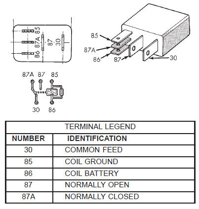 Fig. 8 Compressor Clutch Relay
Electronic cycling clutch switch (front unit only)
Dodge Durango (DN) 1998-2003 Service Manual
- Lubrication and Maintenance
- Suspension
- Differential and Driveline
- Brakes
- Cooling System
- Battery
- Starting Systems
- Charging System
- Ignition System
- Instrument Panel Systems
- Audio Systems
- Horn Systems
- Speed Control System
- Turn Signal and Hazard Warning Systems
- Wiper and Washer Systems
- Lamps
- Passive Restraint Systems
- Electrically Heated Systems
- Power Distribution System
- Power Lock Systems
- Vehicle Theft/Security Systems
- Power Seat System
- Power Window Systems
- Power Mirror Systems
- Chime/Buzzer Warning Systems
- Overhead Console Systems
- Engine
- Exhaust System
- Frame and Bumpers
- Fuel System
- Steering
- Transmission and Transfer Case
- Tires and Wheels
- Body
- Heating and Air Conditioning
- Emission Control Systems
- Introduction
Categories
