Instrument panel top cover
WARNING: ON VEHICLES EQUIPPED WITH AIRBAGS, REFER TO GROUP 8M - PASSIVE RESTRAINT SYSTEMS BEFORE ATTEMPTING ANY STEERING WHEEL, STEERING COLUMN, OR INSTRUMENT PANEL COMPONENT DIAGNOSIS OR SERVICE. FAILURE TO TAKE THE PROPER PRECAUTIONS COULD RESULT IN ACCIDENTAL AIRBAG DEPLOYMENT AND POSSIBLE PERSONAL INJURY.
REMOVAL
(1) Disconnect and isolate the battery negative cable.
(2) Remove the cluster bezel from the instrument panel. Refer to Cluster Bezel in the Removal and Installation section of this group for the procedures.
(3) Remove the park brake release handle from the instrument panel. Refer to Park Brake Release Handle in the Removal and Installation section of this group for the procedures.
(4) Remove the glove box from the instrument panel. Refer to Glove Box in the Removal and Installation section of this group for the procedures.
(5) Remove the glove box lamp and switch from the instrument panel. Refer to Glove Box Lamp and Switch in the Removal and Installation section of this group for the procedures.
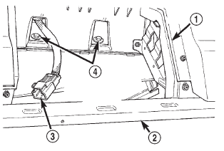
(6) Reach through and above the instrument panel glove box opening to remove the two screws that secure the passenger side airbag module lower bracket to the instrument panel (Fig. 26).
(7) Reach through and above the instrument panel glove box opening to access and disconnect the passenger side airbag module wire harness connector from the instrument panel wire harness.
(8) Disengage the passenger side airbag module wire harness connector retainer from the back of the instrument panel inboard glove box opening bracket.
(9) Remove the heater and air conditioner control from the instrument panel. Refer to Heater-A/C Control in the Removal and Installation section of Group 24 - Heating and Air Conditioning for the procedures.
(10) Reach through the instrument panel heater- A/C control opening to remove the screw that secures the flexible demister tube to the demister duct tee, and remove the tube from the tee.
(11) Reach through the instrument panel heater- A/C control opening to remove the screw that secures the demister duct tee to the instrument panel.
 Fig. 26 Passenger Side Airbag Module Lower Bracket Screws
1 - GLOVE BOX OPENING
2 - LOWER INSTRUMENT PANEL REINFORCEMENT
3 - AIRBAG MODULE WIRE HARNESS CONNECTOR
4 - PASSENGER SIDE AIRBAG MODULE LOWER BRACKET SCREWS
(12) Remove the instrument panel from the vehicle.
Refer to Instrument Panel Assembly in the Removal and Installation section of this group for the procedures.
(13) Place the instrument panel on a suitable work surface. Be certain to take the proper precautions to protect the instrument panel from any possible cosmetic damage.
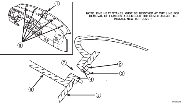
(14) Use a drill motor with a large drill bit, a highspeed grinder, or a soldering iron with a cutting tip to remove the collapsed heat stakes from the underside of the five instrument panel to dash panel mounting screw holes at or below the illustrated cut line (Fig. 27). If the instrument panel top cover is to be reused, use care not to drill through or to enlarge the screw holes in the top cover. To prevent the removal of too much material, use a trim stick or another suitable wide flat-bladed tool to gently pry between the top cover and the instrument panel base bracket near the heat stake during the removal process.
This will cause the panels to separate noticeably when the collapsed heat stake has been sufficiently removed. After removal, the heat stakes should be flush with, or protruding no more than 4 millimeters (0.1875 inches) from the lower surface of the top cover.
 Fig. 27 Instrument Panel Top Cover Remove/Install
1 - AREA OF DETAIL
2 - COMPRESSED HEAT STAKE (FACTORY ASSEMBLED TOP COVER)
3 - HEAT STAKE (NEW TOP COVER)
4 - CUT LINE (REMOVE UNSHADED MATERIAL)
5 - INSTRUMENT PANEL BASE
6 - INSTRUMENT PANEL TOP COVER
7 - MOUNTING SCREW HOLE
8 - FIVE HEAT STAKE LOCATIONS
(15) Remove the screws around the perimeter of the top cover that secure it to the instrument panel base.
(16) Lift the top cover off of the instrument panel.
INSTALLATION
WARNING: USE EXTREME CARE TO PREVENT ANY FOREIGN MATERIAL FROM ENTERING THE PASSENGER SIDE AIRBAG MODULE, OR BECOMING ENTRAPPED BETWEEN THE INSTRUMENT PANEL TOP COVER AND THE PASSENGER SIDE AIRBAG MODULE. FAILURE TO OBSERVE THIS WARNING COULD RESULT IN OCCUPANT INJURIES UPON AIRBAG DEPLOYMENT
NOTE: New instrument panel top covers are supplied with heat stakes that have not been collapsed.
These non-collapsed heat stakes must also be removed in order to install the new top cover. Use a hack saw or razor knife to remove the non-collapsed heat stakes from a new top cover. See Step 14 in the Removal procedure for the heat stake removal details.
(1) Position the top cover onto the instrument panel.
(2) Install and tighten the screws around the perimeter of the top cover that secure it to the instrument panel base. Tighten the screws to 2.2 N*m (20 in. lbs.).
(3) Install the instrument panel into the vehicle.
Refer to Instrument Panel Assembly in the Removal and Installation section of this group for the procedures.
(4) Reach through the instrument panel heater- A/C control opening to install and tighten the screw that secures the demister duct tee to the instrument panel. Tighten the screw to 2.2 N*m (20 in. lbs.).
(5) Reach through the instrument panel heater- A/C control opening to install and tighten the screw that secures the flexible demister tube to the demister duct tee, and remove the tube from the tee.
Tighten the screw to 2.2 N*m (20 in. lbs.).
(6) Install the heater and air conditioner control onto the instrument panel. Refer to Heater-A/C Control in the Removal and Installation section of Group 24 - Heating and Air Conditioning for the procedures.
(7) Engage the passenger side airbag module wire harness connector retainer onto the back of the instrument panel inboard glove box opening bracket.
(8) Reach through and above the instrument panel glove box opening to access and reconnect the passenger side airbag module wire harness connector to the instrument panel wire harness.
(9) Reach through and above the instrument panel glove box opening to install and tighten the two screws that secure the passenger side airbag module lower bracket to the instrument panel. Tighten the screws to 11.8 N*m (105 in. lbs.).
(10) Install the glove box lamp and switch onto the instrument panel. Refer to Glove Box Lamp and Switch in the Removal and Installation section of this group for the procedures.
(11) Install the glove box onto the instrument panel. Refer to Glove Box in the Removal and Installation section of this group for the procedures.
(12) Install the park brake release handle onto the instrument panel. Refer to Park Brake Release Handle in the Removal and Installation section of this group for the procedures.
(13) Install the cluster bezel onto the instrument panel. Refer to Cluster Bezel in the Removal and Installation section of this group for the procedures.
(14) Reconnect the battery negative cable.
Dodge Durango (DN) 1998-2003 Service Manual
- Lubrication and Maintenance
- Suspension
- Differential and Driveline
- Brakes
- Cooling System
- Battery
- Starting Systems
- Charging System
- Ignition System
- Instrument Panel Systems
- Audio Systems
- Horn Systems
- Speed Control System
- Turn Signal and Hazard Warning Systems
- Wiper and Washer Systems
- Lamps
- Passive Restraint Systems
- Electrically Heated Systems
- Power Distribution System
- Power Lock Systems
- Vehicle Theft/Security Systems
- Power Seat System
- Power Window Systems
- Power Mirror Systems
- Chime/Buzzer Warning Systems
- Overhead Console Systems
- Engine
- Exhaust System
- Frame and Bumpers
- Fuel System
- Steering
- Transmission and Transfer Case
- Tires and Wheels
- Body
- Heating and Air Conditioning
- Emission Control Systems
- Introduction
