Instrument panel assembly
WARNING: ON VEHICLES EQUIPPED WITH AIRBAGS, REFER TO GROUP 8M - PASSIVE RESTRAINT SYSTEMS BEFORE ATTEMPTING ANY STEERING WHEEL, STEERING COLUMN, OR INSTRUMENT PANEL COMPONENT DIAGNOSIS OR SERVICE. FAILURE TO TAKE THE PROPER PRECAUTIONS COULD RESULT IN ACCIDENTAL AIRBAG DEPLOYMENT AND POSSIBLE PERSONAL INJURY.
REMOVAL
NOTE: Before starting this procedure, be certain to turn the steering wheel until the front wheels are in the straight-ahead position.
(1) Disconnect and isolate the battery negative cable.
(2) Remove the trim from the right and left front door sills. Refer to Door Sill Trim Cover in the Removal and Installation section of Group 23 - Body for the procedures.
(3) Remove the trim from the left and right cowl side inner panels. Refer to Cowl Trim Cover in the Removal and Installation section of Group 23 - Body for the procedures.
(4) Remove the steering column opening cover from the instrument panel. Refer to Steering Column Opening Cover in the Removal and Installation section of this group for the procedures.
(5) Remove the two screws that secure the inside hood latch release handle to the instrument panel lower reinforcement and lower the release handle to the floor.
(6) Disconnect the driver side airbag module wire harness connector from the instrument panel wire harness at the instrument panel lower reinforcement.
(7) If the vehicle is so equipped, disconnect the overdrive lockout switch wire harness connector from the instrument panel wire harness near the instrument panel lower reinforcement.
(8) Remove the steering column from the vehicle, but do not remove the driver side airbag module, the steering wheel, or the switches from the steering column.
Be certain that the steering wheel is locked and secured from rotation to prevent the loss of clockspring centering. Refer to Steering Column in the Removal and Installation section of Group 19 - Steering for the procedures.
(9) From under the driver side of the instrument panel, perform the following: (a) Remove the screw from the center of the headlamp and dash to instrument panel bulkhead wire harness connector and disconnect the connector.
(b) Disconnect the two body wire harness connectors from the two instrument panel wire harness connectors that are secured to the outboard side of the instrument panel bulkhead connector.
(c) Disconnect the three wire harness connectors (one from the body wire harness, and two from the headlamp and dash wire harness) from the three junction block connector receptacles located closest to the dash panel.
(d) Unsnap the plastic retainer clip that secures the park brake release linkage rod to the lever on the back side of the park brake release handle and disengage the linkage rod end from the lever on the handle.
(e) Disconnect the instrument panel wire harness connector from the stop lamp switch connector receptacle.
(f) Disconnect the vacuum harness connector located near the left end of the heater-A/C housing.
(10) Remove the center support bracket from the instrument panel. Refer to Instrument Panel Center Support Bracket in the Removal and Installation section of this group for the procedures.
(11) Remove the screw that secures the instrument panel wire harness ground eyelets to the left side of the Airbag Control Module (ACM) mount on the floor panel transmission tunnel.
(12) Disconnect the instrument panel wire harness connector from the ACM connector receptacle.
(13) Remove the glove box from the instrument panel. Refer to Glove Box in the Removal and Installation section of this group for the procedures.
(14) Reaching through the instrument panel glove box opening, perform the following: (a) Disconnect the two halves of the radio antenna coaxial cable connector near the center of the lower instrument panel glove box opening.
(b) Disengage the antenna half of the radio antenna coaxial cable from the retainer clip near the outboard side of the lower instrument panel glove box opening.
(c) Disconnect the blower motor wire harness connector located near the heater-A/C housing support brace on the inboard side of the instrument panel glove box opening.
(15) From under the passenger side of the instrument panel, perform the following: (a) If the vehicle is so equipped, disconnect the two instrument panel wire harness connectors from the Infinity speaker amplifier connector receptacles on the right cowl side inner panel.
(b) Remove the nut that secures the instrument panel wire harness radio ground eyelet to the stud on the right cowl side inner panel.
(16) Loosen the right and left instrument panel cowl side roll-down bracket screws about 6 mm (0.25 inch) (Fig. 24).
(17) Remove the five screws that secure the top of the instrument panel to the top of the dash panel, removing the center screw last.
(18) Pull the lower instrument panel rearward until the right and left cowl side roll-down bracket screws are in the roll-down slot position of both brackets (Fig. 25).
(19) Roll down the instrument panel and install a temporary hook in the center hole on top of the instrument panel. Secure the other end of the hook to the center hole in the top of the dash panel. The hook should support the instrument panel in its rolled down position about 46 cm (18 inches) from the dash panel.
(20) With the instrument panel supported in the roll-down position: (a) Disconnect the two instrument panel wire harness connectors from the door jumper wire harness connectors located on a bracket near the right end of the instrument panel.
(b) Disconnect the instrument panel wire harness connector from the blower motor resistor connector receptacle on the dash panel.
(c) Disconnect the temperature control cable flag retainer from the top of the heater-A/C housing and pull the cable core adjuster clip off of the blend-air door lever.
(d) Disconnect the demister duct flexible hose from the adapter on the top of the heater-A/C housing.
(21) With the aid of an assistant, remove the temporary hook and lift the instrument panel assembly off of the roll-down bracket screws and remove it from the vehicle.
INSTALLATION
(1) With the aid of an assistant, install the instrument panel assembly onto the roll-down bracket screws in the vehicle. Install a temporary hook in the center hole on top of the instrument panel. Secure the other end of the hook to the center hole in the top of the dash panel. The hook should support the instrument panel in its rolled down position about 46 cm (18 inches) from the dash panel.
(2) With the instrument panel supported in the roll-down position: (a) Reconnect the two instrument panel wire harness connectors to the door jumper wire harness connectors located on a bracket near the right end of the instrument panel.
(b) Reconnect the instrument panel wire harness connector to the blower motor resistor connector receptacle on the dash panel.
(c) Reconnect the temperature control cable flag retainer onto the top of the heater-A/C housing and push the cable core adjuster clip onto the blend-air door lever.
(d) Reconnect the demister duct flexible hose to the adapter on the top of the heater-A/C housing.
(3) Push the lower instrument panel forward until the right and left cowl side roll-down bracket screws are in the installed slot position of both brackets (Fig. 25).
(4) Remove the temporary hook from the instrument panel and roll the instrument panel up to the installed position against the dash panel.
(5) Install and tighten the five screws that secure the top of the instrument panel to the top of the dash panel. Tighten the screws to 3.2 N*m (28 in. lbs.).
(6) Tighten the right and left instrument panel cowl side roll-down bracket screws. Tighten the screws to 11.9 N*m (105 in. lbs.).
(7) From under the passenger side of the instrument panel, perform the following:
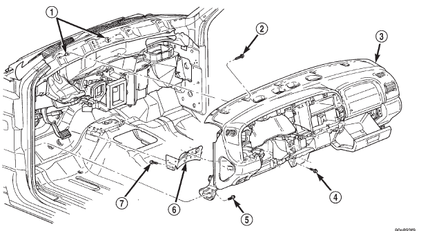 Fig. 24 Instrument Panel Assembly Remove/Install
1 - CLIPS
2 - SCREW
3 - INSTRUMENT PANEL
4 - SCREW
5 - SCREW
6 - CENTER SUPPORT BRACKET
7 - SCREW
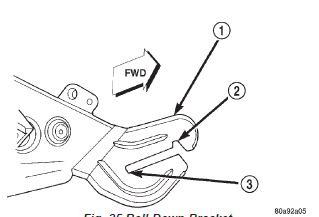 Fig. 25 Roll-Down Bracket
1 - ROLL - DOWN BRACKET
2 - ROLL - DOWN SLOT
3 - INSTALLED SLOT
(a) If the vehicle is so equipped, reconnect the two instrument panel wire harness connectors to the Infinity speaker amplifier connector receptacles on the right cowl side inner panel.
(b) Install and tighten the nut that secures the instrument panel wire harness radio ground eyelet to the stud on the right cowl side inner panel.
Tighten the nut to 3.9 N*m (35 in. lbs.).
(8) Reaching through the instrument panel glove box opening, perform the following: (a) Reconnect the two halves of the radio antenna coaxial cable connector near the center of the lower instrument panel glove box opening.
(b) Engage the antenna half of the radio antenna coaxial cable into the retainer clip near the outboard side of the lower instrument panel glove box opening.
(c) Reconnect the blower motor wire harness connector located near the heater-A/C housing support brace on the inboard side of the instrument panel glove box opening.
(9) Install the glove box onto the instrument panel.
Refer to Glove Box in the Removal and Installation section of this group for the procedures.
(10) Install and tighten the screw that secures the instrument panel wire harness ground eyelets to the left side of the Airbag Control Module (ACM) mount on the floor panel transmission tunnel. Tighten the screw to 3.4 N*m (30 in. lbs.).
(11) Reconnect the instrument panel wire harness connector to the ACM connector receptacle.
(12) Install the center support bracket onto the instrument panel. Refer to Instrument Panel Cen-ter Support Bracket in the Removal and Installation section of this group for the procedures.
(13) From under the driver side of the instrument panel, perform the following: (a) Reconnect the headlamp and dash to instrument panel bulkhead wire harness connector and tighten the screw in the center of the connector.
Tighten the screw to 3.5 N*m (31 in. lbs.).
(b) Reconnect the two body wire harness connectors to the two instrument panel wire harness connectors that are secured to the outboard side of the instrument panel bulkhead connector.
(c) Reconnect the three wire harness connectors (one from the body wire harness, and two from the headlamp and dash wire harness) to the three junction block connector receptacles located closest to the dash panel.
(d) Engage the linkage rod end into the lever on the back side of the park brake release handle and snap the plastic retainer clip over the linkage rod that secures it to the lever.
(e) Reconnect the instrument panel wire harness connector to the stop lamp switch connector receptacle.
(f) Reconnect the vacuum harness connector located near the left end of the heater-A/C housing.
(14) Install the steering column into the vehicle.
Be certain that the steering wheel was locked and secured from rotation to prevent the loss of clockspring centering. Refer to Steering Column in the Removal and Installation section of Group 19 - Steering for the procedures.
(15) If the vehicle is so equipped, reconnect the overdrive lockout switch wire harness connector to the instrument panel wire harness near the instrument panel lower reinforcement.
(16) Reconnect the driver side airbag module wire harness connector to the instrument panel wire harness at the instrument panel lower reinforcement.
(17) Position the inside hood latch release handle to the instrument panel lower reinforcement.
(18) Install and tighten the two screws that secure the inside hood latch release handle to the instrument panel lower reinforcement. Tighten the screws to 2.8 N*m (25 in. lbs.).
(19) Install the steering column opening cover onto the instrument panel. Refer to Steering Column Opening Cover in the Removal and Installation section of this group for the procedures.
(20) Install the trim onto the left and right cowl side inner panels. Refer to Cowl Trim Cover in the Removal and Installation section of Group 23 - Body for the procedures.
(21) Install the trim onto the right and left front door sills. Refer to Door Sill Trim Cover in the Removal and Installation section of Group 23 - Body for the procedures.
(22) Reconnect the battery negative cable.
Dodge Durango (DN) 1998-2003 Service Manual
- Lubrication and Maintenance
- Suspension
- Differential and Driveline
- Brakes
- Cooling System
- Battery
- Starting Systems
- Charging System
- Ignition System
- Instrument Panel Systems
- Audio Systems
- Horn Systems
- Speed Control System
- Turn Signal and Hazard Warning Systems
- Wiper and Washer Systems
- Lamps
- Passive Restraint Systems
- Electrically Heated Systems
- Power Distribution System
- Power Lock Systems
- Vehicle Theft/Security Systems
- Power Seat System
- Power Window Systems
- Power Mirror Systems
- Chime/Buzzer Warning Systems
- Overhead Console Systems
- Engine
- Exhaust System
- Frame and Bumpers
- Fuel System
- Steering
- Transmission and Transfer Case
- Tires and Wheels
- Body
- Heating and Air Conditioning
- Emission Control Systems
- Introduction
Categories
