Asd and fuel pump relays. Throttle body minimum air flow check procedure
The following description of operation and
tests apply only to the Automatic Shutdown
(ASD) and fuel pump relays. The terminals on the
bottom of each relay are numbered (Fig. 13).
OPERATIONAsd and fuel pump relays
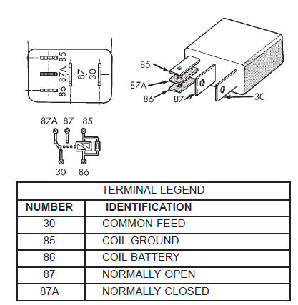 Fig. 13 ASD and Fuel Pump Relay Terminals
For both the ASD and fuel pump relays, terminal 30 is connected to battery voltage at all times.
This is the On position. Terminal 87 supplies voltage to the rest of the circuit.
TESTING
The following procedure applies to the ASD and fuel pump relays.
(1) Remove relay from connector before testing.
(2) With the relay removed from the vehicle, use an ohmmeter to check the resistance between terminals 85 and 86. The resistance should be 75 65 ohms.
(3) Connect the ohmmeter between terminals 30 and 87A. The ohmmeter should show continuity between terminals 30 and 87A.
(4) Connect the ohmmeter between terminals 87 and 30. The ohmmeter should not show continuity at this time.
(5) Connect one end of a jumper wire (16 gauge or smaller) to relay terminal 85. Connect the other end of the jumper wire to the ground side of a 12 volt power source.
(6) Connect one end of another jumper wire (16 gauge or smaller) to the power side of the 12 volt power source. Do not attach the other end of the jumper wire to the relay at this time.
WARNING: DO NOT ALLOW OHMMETER TO CONTACT TERMINALS 85 OR 86 DURING THIS TEST.
(7) Attach the other end of the jumper wire to relay terminal 86. This activates the relay. The ohmmeter should now show continuity between relay terminals 87 and 30. The ohmmeter should not show continuity between relay terminals 87A and 30.
(8) Disconnect jumper wires.
(9) Replace the relay if it did not pass the continuity and resistance tests. If the relay passed the tests, it operates properly. Check the remainder of the ASD and fuel pump relay circuits. Refer to group 8W, Wiring Diagrams.
Throttle body minimum air flow check procedure
3.9/5.2/5.9L ENGINES
The following test procedure has been developed to check throttle body calibrations for correct idle conditions.
The procedure should be used to diagnose the throttle body for conditions that may cause idle problems.
This procedure should be used only after normal diagnostic procedures have failed to produce results that indicate a throttle body related problem. Be sure to check for proper operation of the idle air control motor before performing this test.
A special fixed orifice tool (number 6714) (Fig. 14) must be used for the following test.
 Fig. 14 Fixed Orifice Tool
(1) Start the engine and bring to operating temperature.
Be sure all accessories are off before performing this test.
(2) Shut off the engine and remove the air duct at throttle body.
(3) Disconnect the vacuum line at the PCV valve (Fig. 15).
 Fig. 15 Install Orifice Tool
1 - PCV VALVE
2 - VACUUM LINE
3 - ORIFICE TOOL
(4) Install the 0.185 inch orifice tool (number 6714) into the disconnected vacuum line in place of the PCV valve (Fig. 15).
(5) Disconnect the idle purge vacuum line from fitting at throttle body. This vacuum line is located on the front of throttle body next to the MAP sensor (Fig. 16). Cap the fitting at throttle body after vacuum line has been removed.
 Fig. 16 Idle Purge Line
1 - THROTTLE BODY
2 - PURGE VACUUM LINE
(6) Connect the DRB scan tool to the 16-way data link connector. This connector is located under the instrument panel to the left of the steering column.
Refer to the appropriate Powertrain Diagnostic Procedures service manual for DRB operation.
(7) Start the engine and allow to warm up.
(8) Using the DRB scan tool, scroll through the menus as follows: select-Stand Alone DRB III, select the year 2000 Diagnostics, select-Engine, select- System Test, select-Minimum Air Flow.
(9) The DRB scan tool will count down to stabilize the idle rpm and display the minimum air flow idle rpm. The idle rpm should be between 500 and 900 rpm. If the idle speed is outside of these specifications, replace the throttle body. Refer to Throttle Body in the Component Removal/Installation section of this group.
(10) Disconnect the DRB scan tool from the vehicle.
(11) Remove cap from idle purge fitting at throttle body and install vacuum line.
(12) Remove orifice tool and connect vacuum line to PCV valve.
(13) Install air duct to throttle body.
Dodge Durango (DN) 1998-2003 Service Manual
- Lubrication and Maintenance
- Suspension
- Differential and Driveline
- Brakes
- Cooling System
- Battery
- Starting Systems
- Charging System
- Ignition System
- Instrument Panel Systems
- Audio Systems
- Horn Systems
- Speed Control System
- Turn Signal and Hazard Warning Systems
- Wiper and Washer Systems
- Lamps
- Passive Restraint Systems
- Electrically Heated Systems
- Power Distribution System
- Power Lock Systems
- Vehicle Theft/Security Systems
- Power Seat System
- Power Window Systems
- Power Mirror Systems
- Chime/Buzzer Warning Systems
- Overhead Console Systems
- Engine
- Exhaust System
- Frame and Bumpers
- Fuel System
- Steering
- Transmission and Transfer Case
- Tires and Wheels
- Body
- Heating and Air Conditioning
- Emission Control Systems
- Introduction
Categories
