Remote radio switch. Speaker
For complete circuit diagrams, refer to Audio System
in the Contents of Group 8W - Wiring Diagrams. WARNING: ON VEHICLES EQUIPPED WITH AIRBAGS,
REFER TO GROUP 8M - PASSIVE
RESTRAINT SYSTEMS BEFORE ATTEMPTING ANY
STEERING WHEEL, STEERING COLUMN, OR
INSTRUMENT PANEL COMPONENT DIAGNOSIS OR
SERVICE. FAILURE TO TAKE THE PROPER PRECAUTIONS
COULD RESULT IN ACCIDENTAL AIRBAG
DEPLOYMENT AND POSSIBLE PERSONAL
INJURY. (1) Remove the remote radio switch(es) (Fig. 2)
from the steering wheel.
1 - WHITE REAR SWITCH 2 - BLACK REAR SWITCH (2) Use an ohmmeter to check the switch resistances
as shown in the Remote Radio Switch Test
chart. If the remote radio switch resistances check
OK, go to Step 3. If not OK, replace the faulty
switch. (3) Check for continuity between the ground circuit
cavity of the remote radio switch wire harness
connector and a good ground. There should be continuity.
If OK, go to Step 4. If not OK, repair the open
ground circuit to ground as required.
(4) Disconnect the 18-way wire harness connector
from the Central Timer Module (CTM). Check for
continuity between the radio control mux circuit cavity
of the remote radio switch wire harness connector
and a good ground. There should be no continuity. If
OK, go to Step 5. If not OK, repair the shorted radio
control mux circuit as required. (5) Check for continuity between the radio control
mux circuit cavities of the remote radio switch wire
harness connector and the 18-way CTM wire harness
connector. There should be continuity. If OK, refer to
the proper Diagnostic Procedures manual to test the
CTM and the Chrysler Collision Detection (CCD)
data bus. If not OK, repair the open radio control
mux circuit as required. For complete circuit diagrams, refer to Audio System
in the Contents of Group 8W - Wiring Diagrams. WARNING: ON VEHICLES EQUIPPED WITH AIRBAGS,
REFER TO GROUP 8M - PASSIVE
RESTRAINT SYSTEMS BEFORE ATTEMPTING ANY
STEERING WHEEL, STEERING COLUMN, OR
INSTRUMENT PANEL COMPONENT DIAGNOSIS OR
SERVICE. FAILURE TO TAKE THE PROPER PRECAUTIONS
COULD RESULT IN ACCIDENTAL AIRBAG
DEPLOYMENT AND POSSIBLE PERSONAL
INJURY. CAUTION: The speaker output of the radio is a
"floating ground" system. Do not allow any speaker
lead to short to ground, as damage to the radio
may result. (1) Turn the ignition switch to the On position.
Turn the radio receiver on. Adjust the balance and
fader controls to check the performance of each individual
speaker. Note the speaker locations that are
not performing correctly. Go to Step 2.
(2) Turn the radio receiver off. Turn the ignition
switch to the Off position. Disconnect and isolate the
battery negative cable. Remove the radio receiver
from the instrument panel. If the vehicle is equipped
with the Infinity speaker package, also disconnect
the wire harness connectors at the power amplifier.
Check both the speaker feed (+) circuit and return (-)
circuit cavities for the inoperative speaker location(s)
at the radio receiver wire harness connectors for continuity
to ground. In each case, there should be no
continuity. If OK, go to Step 3. If not OK, repair the
shorted speaker feed (+) and/or return (-) circuit(s) to
the speaker as required.
(3) If the vehicle is equipped with the Infinity
speaker package, go to Step 6. If the vehicle is
equipped with the standard speaker system, check
the resistance between the speaker feed (+) circuit
and return (-) circuit cavities of the radio receiver
wire harness connectors for the inoperative speaker
location(s). The meter should read between 2 and 28
ohms (speaker resistance). If OK, go to Step 4. If not
OK, go to Step 5. (4) Install a known good radio receiver. Connect
the battery negative cable. Turn the ignition switch
to the On position. Turn on the radio receiver and
test the speaker operation. If OK, replace the faulty
radio receiver. If not OK, turn the radio receiver off,
turn the ignition switch to the Off position, disconnect
and isolate the battery negative cable, remove
the test radio receiver, and go to Step 5.
(5) Disconnect the wire harness connector at the
inoperative speaker. Check for continuity between
the speaker feed (+) circuit cavities of the radio
receiver wire harness connector and the speaker wire
harness connector. Repeat the check between the
speaker return (-) circuit cavities of the radio
receiver wire harness connector and the speaker wire
harness connector. In each case, there should be continuity.
If OK, replace the faulty speaker. If not OK,
repair the open speaker feed (+) and/or return (-) circuit(
s) as required.
(6) For each inoperative speaker location, check for
continuity between the speaker feed (+) circuit cavities
of the radio receiver wire harness connectors and
the power amplifier wire harness connectors. Repeat
the check for each inoperative speaker location
between the speaker return (-) circuit cavities of the
radio receiver wire harness connectors and the power
amplifier wire harness connectors. In each case,
there should be continuity. If OK, go to Step 7. If not
OK, repair the open speaker feed (+) and/or return
(-) circuit(s) as required.
(7) Check for continuity between the two ground
circuit cavities of the power amplifier wire harness
connector and a good ground. There should be continuity.
If OK, go to Step 8. If not OK, repair the open
ground circuit(s) to ground as required.
(8) Check the power amplifier fuse in the junction
block. If OK, go to Step 9. If not OK, repair the
shorted circuit or component as required and replace
the faulty fuse.
(9) Install the radio receiver. Connect the battery
negative cable. Check for battery voltage at the
power amplifier fuse in the junction block. If OK, go
to Step 10. If not OK, repair the open fused B(+) circuit
to the PDC as required.
(10) Check for battery voltage at the two fused
B(+) circuit cavities of the power amplifier wire harness
connector. If OK, go to Step 11. If not OK, repair
the open fused B(+) circuit(s) to the fuse in the junction
block as required.
(11) Turn the ignition switch to the On position.
Turn the radio receiver on. Check for battery voltage
at the radio 12 volt output circuit cavity of the power
amplifier wire harness connector. If OK, go to Step
12. If not OK, repair the open radio 12 volt output
circuit to the radio receiver as required.
(12) Turn the radio receiver off. Turn the ignition
switch to the Off position. Disconnect and isolate the
battery negative cable. For each inoperative speaker
location, check both the amplified feed (+) circuit and
the amplified return (-) circuit cavities of the power
amplifier wire harness connectors for continuity to
ground. In each case there should be no continuity. If
OK, go to Step 13. If not OK, repair the shorted
amplified feed (+) and/or amplified return (-) circuit(
s) to the speaker as required.
(13) For each inoperative speaker location, check
the resistance between the amplified feed (+) circuit
and the amplified return (-) circuit cavities of the
power amplifier wire harness connectors. The meter
should read between 2 and 28 ohms (speaker resistance).
If OK, replace the faulty power amplifier. If
not OK, go to Step 14.
(14) Disconnect the speaker wire harness connector
at the inoperative speaker. Check for continuity
between the amplified feed (+) circuit cavities of the
speaker wire harness connector and the power amplifier
wire harness connector. Repeat the check
between the amplified return (-) circuit cavities of
the speaker wire harness connector and the power
amplifier wire harness connector. In each case there
should be continuity. If OK, replace the faulty
speaker. If not OK, repair the open amplified feed (+)
and/or amplified return (-) circuit(s) as required. Power amplifier The power amplifier unit should be checked if
there is no sound output noted from the speakers.
For diagnosis of the power amplifier, refer to
Speaker in the Diagnosis and Testing section of this
group. For complete circuit diagrams, refer to Audio
System in the Contents of Group 8W - Wiring Diagrams.Remote radio switch
 Fig. 2 Remote Radio Switches
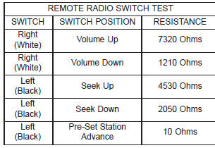
Speaker
Dodge Durango (DN) 1998-2003 Service Manual
- Lubrication and Maintenance
- Suspension
- Differential and Driveline
- Brakes
- Cooling System
- Battery
- Starting Systems
- Charging System
- Ignition System
- Instrument Panel Systems
- Audio Systems
- Horn Systems
- Speed Control System
- Turn Signal and Hazard Warning Systems
- Wiper and Washer Systems
- Lamps
- Passive Restraint Systems
- Electrically Heated Systems
- Power Distribution System
- Power Lock Systems
- Vehicle Theft/Security Systems
- Power Seat System
- Power Window Systems
- Power Mirror Systems
- Chime/Buzzer Warning Systems
- Overhead Console Systems
- Engine
- Exhaust System
- Frame and Bumpers
- Fuel System
- Steering
- Transmission and Transfer Case
- Tires and Wheels
- Body
- Heating and Air Conditioning
- Emission Control Systems
- Introduction
Categories
