Low pressure cut-off switch. Mode door vacuum actuator
REMOVAL (1) Disconnect and isolate the battery negative
cable.
(2) Unplug the wire harness connector from the
low pressure cut-off switch on the suction line jumper
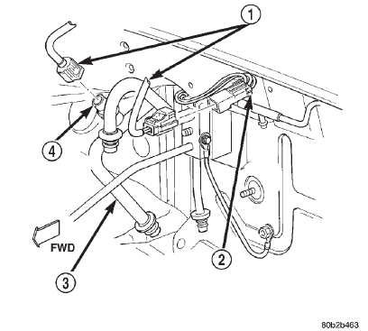
near the expansion valve (Fig. 75).
1 - WIRE HARNESS CONNECTORS 2 - TO ELECTRONIC CYCLING CLUTCH SWITCH 3 - SUCTION LINE JUMPER 4 - LOW PRESSURE CUT-OFF SWITCH (3) Unscrew the low pressure cut-off switch from
the fitting on the suction line jumper. (4) Remove the O-ring seal from the suction line
jumper fitting and discard. INSTALLATION (1) Lubricate a new O-ring seal with clean refrigerant
oil and install it on the suction line jumper fitting.
Use only the specified O-rings as they are made
of a special material for the R-134a system. Use only
refrigerant oil of the type recommended for the compressor
in the vehicle.
(2) Install and tighten the low pressure cut-off
switch on the suction line jumper fitting. The switch
should be hand-tightened onto the fitting.
(3) Plug the wire harness connector into the low
pressure cut-off switch.
(4) Connect the battery negative cable. WARNING: ON VEHICLES EQUIPPED WITH AIRBAGS,
REFER TO GROUP 8M - PASSIVE
RESTRAINT SYSTEMS BEFORE ATTEMPTING ANY
STEERING WHEEL, STEERING COLUMN, OR
INSTRUMENT PANEL COMPONENT DIAGNOSIS OR
SERVICE. FAILURE TO TAKE THE PROPER PRECAUTIONS
COULD RESULT IN ACCIDENTAL AIRBAG
DEPLOYMENT AND POSSIBLE PERSONAL
INJURY. FLOOR-DEFROST DOOR ACTUATOR (1) Disconnect and isolate the battery negative
cable.
(2) Remove the instrument panel assembly from
the vehicle. Refer to Instrument Panel Assembly in
the Removal and Installation section of Group 8E -
Instrument Panel Systems for the procedures.
(3) Unplug the two vacuum harness connectors
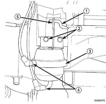
from the floor-defrost door actuator (Fig. 76).
(4) Remove the push nut retainer that secures the
floor-defrost door actuator link to the floor-defrost
door crank arm.
(5) Remove the two screws that secure the floordefrost
door actuator to the heater-A/C housing.
(6) Disengage the floor-defrost door actuator link
from the floor-defrost door crank arm and remove the
actuator from the heater-A/C housing.
(7) Reverse the removal procedures to install.
Tighten the floor-defrost door actuator mounting
screws to 2.2 N*m (20 in. lbs.). PANEL-DEFROST DOOR ACTUATOR (1) Disconnect and isolate the battery negative
cable.
(2) Remove the instrument panel assembly from
the vehicle. Refer to Instrument Panel Assembly in the Removal and Installation
section of Group 8E -
Instrument Panel Systems for the procedures.
(3) Unplug the vacuum harness connector from the
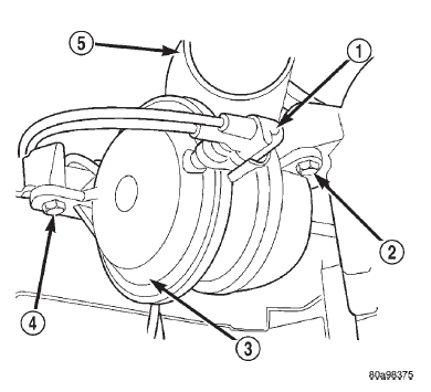
panel-defrost door actuator (Fig. 77).
(4) Remove the two screws that secure the paneldefrost
door actuator to the heater-A/C housing.
(5) Rotate the panel-defrost door actuator clockwise
about one-quarter turn to disengage the hooked
end of the actuator link from the hole on the end of
the panel-defrost door lever.
(6) Remove the panel-defrost door actuator from
the heater-A/C housing.
(7) Reverse the removal procedures to install.
Tighten the panel-defrost door actuator mounting
screws to 2.2 N*m (20 in. lbs.).
1 - FLOOR-DEFROST DOOR CRANK ARM 2 - SCREWS 3 - FLOOR-DEFROST DOOR ACTUATOR 4 - VACUUM CONNECTORS 5 - PUSH NUT RECIRCULATION AIR DOOR ACTUATOR A recirculation air door and vacuum actuator are
used only on models with the optional air conditioning
system.
(1) Disconnect and isolate the battery negative
cable.
(2) Remove the instrument panel assembly from
the vehicle. Refer to Instrument Panel Assembly in
the Removal and Installation section of Group 8E -
Instrument Panel Systems for the procedures.
(3) If the vehicle is so equipped, and the heater-
A/C housing is in its installed position in the vehicle,
remove the Infinity speaker system amplifier. Refer
to Amplifier in the Removal and Installation section
of Group 8F - Audio Systems for the procedures.
(4) Unplug the two vacuum harness connectors
from the recirculation air door actuator (Fig. 78).
(5) Remove the two stamped nuts that secure the
recirculation air door actuator to the blower motor
housing cover.
(6) Unhook the actuator link from the recirculation
air door lever.
(7) Remove the actuator from the blower motor
housing cover.
(8) Reverse the removal procedures to install.
Tighten the mounting nuts until the recirculation air
door actuator is seated to the blower motor housing
cover.
1 - VACUUM CONNECTOR 2 - SCREW 3 - PANEL-DEFROST DOOR ACTUATOR 4 - SCREW 5 - DEMISTER DUCT ADAPTERLow pressure cut-off switch
 Fig. 75 Low Pressure Cut-Off Switch Remove/Install
Mode door vacuum actuator
 Fig. 76 Floor-Defrost Door Actuator Remove/Install
 Fig. 77 Panel-Defrost Door Actuator
Dodge Durango (DN) 1998-2003 Service Manual
- Lubrication and Maintenance
- Suspension
- Differential and Driveline
- Brakes
- Cooling System
- Battery
- Starting Systems
- Charging System
- Ignition System
- Instrument Panel Systems
- Audio Systems
- Horn Systems
- Speed Control System
- Turn Signal and Hazard Warning Systems
- Wiper and Washer Systems
- Lamps
- Passive Restraint Systems
- Electrically Heated Systems
- Power Distribution System
- Power Lock Systems
- Vehicle Theft/Security Systems
- Power Seat System
- Power Window Systems
- Power Mirror Systems
- Chime/Buzzer Warning Systems
- Overhead Console Systems
- Engine
- Exhaust System
- Frame and Bumpers
- Fuel System
- Steering
- Transmission and Transfer Case
- Tires and Wheels
- Body
- Heating and Air Conditioning
- Emission Control Systems
- Introduction
