Electronic cycling clutch switch. Evaporator coil
REMOVAL (1) Disconnect and isolate the battery negative
cable.
(2) Unplug the wire harness connector from the
electronic cycling clutch switch near the expansion
valve (Fig. 49).
1 - ELECTRONIC CYCLING CLUTCH SWITCH 2 - WIRE HARNESS CONNECTOR 3 - EXPANSION VALVE 4 - FASTENER (3) Remove and discard the fastener that secures
the electronic cycling clutch switch to the outboard
side of the expansion valve.
(4) Pull the electronic cycling clutch switch away
from the side of the expansion valve far enough for
the thermistor probe capillary tube to clear the well
in the expansion valve. The washer bottle may have
to be removed. NOTE: The capillary tube well in the expansion
valve is filled with a special thermally-conductive
grease. This grease should be removed from the
old parts and reused on the new parts whenever
the electronic cycling clutch switch or the expansion
valve are replaced. INSTALLATION (1) Insert the thermistor probe capillary tube of
the electronic cycling clutch switch into the well on
the outboard side of the expansion valve. (2) Install the electronic cycling clutch switch to
the expansion valve and secure it with a new fastener.
(3) Plug the wire harness connector into the electronic
cycling clutch switch.
(4) Connect the battery negative cable. WARNING: REVIEW THE WARNINGS AND CAUTIONS
IN THE GENERAL INFORMATION SECTION
NEAR THE FRONT OF THIS GROUP BEFORE PERFORMING
THE FOLLOWING OPERATION. WARNING: ON VEHICLES EQUIPPED WITH AIRBAGS,
REFER TO GROUP 8M - PASSIVE
RESTRAINT SYSTEMS BEFORE ATTEMPTING ANY
STEERING WHEEL, STEERING COLUMN, OR
INSTRUMENT PANEL COMPONENT DIAGNOSIS OR
SERVICE. FAILURE TO TAKE THE PROPER PRECAUTIONS
COULD RESULT IN ACCIDENTAL AIRBAG
DEPLOYMENT AND POSSIBLE PERSONAL
INJURY. FRONT REMOVAL (1) Remove the heater-A/C housing from the vehicle,
and remove the housing cover. See Heater-A/C
Housing in the Removal and Installation section of
this group for the procedures.
(2) Lift the front evaporator coil out of the heater-
A/C housing (Fig. 50).
1 - EVAPORATOR COIL 2 - HEATER-A/C HOUSING INSTALLATION (1) Insert the front evaporator coil into the bottom
of the heater-A/C housing.
(2) Reassemble and reinstall the heater-A/C housing
in the vehicle. See Heater-A/C Housing in the
Removal and Installation section of this group for the
procedures. NOTE: If the front evaporator coil is replaced, add
60 milliliters (2 fluid ounces) of refrigerant oil to the
refrigerant system. Use only refrigerant oil of the
type recommended for the compressor in the vehicle. REAR The rear evaporator coil is used only on models
with the optional rear overhead A/C unit. REMOVAL (1) Disconnect and isolate the battery negative
cable.
(2) Recover the refrigerant from the refrigerant
system. See Refrigerant Recovery in the Service Procedures
section of this group.
(3) Remove the headliner from the passenger compartment
of the vehicle. Refer to Group 23 - Body for
the procedures.
(4) From the passenger compartment, remove the
nuts that secure the block fittings at the top of the
B-pillar refrigerant lines to the studs on the rear
overhead A/C unit, and disengage the fittings (Fig.
51). Install plugs in, or tape over all of the opened
refrigerant line fittings.
(5) Disconnect the B-pillar drain hoses from the
wye fittings on each side of the rear overhead A/C
unit (Fig. 52).
(6) Remove the nine screws that secure the lower
housing cover to the rear overhead A/C unit.
(7) Release the lower housing cover snap retainer
near the center of the outlet side (rear) of the rear
overhead A/C unit (Fig. 53).
(8) Feed the rear blower motor switch wire harness
and connector through the hole in the right end
of the rear overhead A/C unit lower housing cover
while removing the cover from the unit.
(9) Remove the screw that secures the rear overhead
A/C refrigerant tube and block fitting retaining
strap to the right side of the upper housing cover
(Fig. 54).
(10) Remove the two screws that secure the rear
evaporator coil to the rear overhead A/C unit upper
housing cover (Fig. 55).
(11) Remove the rear evaporator coil from the rear
overhead A/C unit.
1 - B-PILLAR SUCTION LINE 2 - B-PILLAR LIQUID LINE 3 - OVERHEAD AIR CONDITIONING UNIT 4 - NUT 5 - STUD 6 - BOLT 7 - NUT
1 - REAR OVERHEAD A/C UNIT 2 - WYE FITTING 3 - CLIP 4 - GROMMET 5 - DRAIN HOSE
1 - REAR OVERHEAD A/C UNIT LOWER HOUSING COVER 2 - SNAP RETAINER 3 - OUTLET SIDE 4 - BLOWER MOTOR SWITCH WIRE HARNESS CONNECTOR 5 - INLET SIDE 6 - DRAIN HOSES
1 - BLOWER WHEEL 2 - RETAINING STRAP 3 - SCREW 4 - EVAPORATOR COIL INSTALLATION (1) Position the rear evaporator coil to the rear
overhead A/C unit and secure with two mounting
screws. Tighten the mounting screws to 2.2 N*m (20
in. lbs.).
(2) Install the rear overhead A/C refrigerant tube
and block fitting retaining strap to the right side of
the upper housing cover and secure with a screw.
Tighten the mounting screws to 2.2 N*m (20 in. lbs.).
1 - BLOWER WHEEL AND HOUSING 2 - SCREWS 3 - EVAPORATOR COIL (3) Feed the rear blower motor switch wire harness
and connector through the hole in the right end
of the rear overhead A/C unit lower housing cover
while positioning the cover to the unit.
(4) Be certain that the lower housing cover snap
retainer near the center of the outlet side (rear) of
the rear overhead A/C unit is engaged.
(5) Install the nine screws that secure the lower
housing cover to the rear overhead A/C unit. Tighten
the mounting screws to 2.2 N*m (20 in. lbs.).
(6) Connect the B-pillar drain hoses to the wye fittings
on each side of the rear overhead A/C unit.
(7) Remove the tape or plugs from block fittings at
the top of the B-pillar refrigerant line unit, and from
the fittings on the rear overhead A/C unit. Install the
B-pillar refrigerant line block fittings over the two
studs on the rear overhead A/C unit and secure the
connections with the mounting nuts. Tighten the
mounting nuts to 11.3 N*m (100 in. lbs.).
(8) Reinstall the headliner in the passenger compartment
of the vehicle. Refer to Group 23 - Body for
the procedures.
(9) Connect the battery negative cable.
(10) Evacuate the refrigerant system. See Refrigerant
System Evacuate in the Service Procedures section
of this group.
(11) Charge the refrigerant system. See Refrigerant
System Charge in the Service Procedures section
of this group. NOTE: If the rear evaporator coil and expansion
valve unit is replaced, add 30 milliliters (1 fluid
ounce) of refrigerant oil to the refrigerant system.
Use only refrigerant oil of the type recommended
for the compressor in the vehicle.Electronic cycling clutch switch
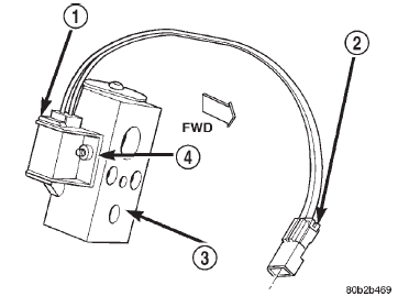 Fig. 49 Electronic Cycling Clutch Switch Remove/ Install
Evaporator coil
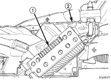 Fig. 50 Evaporator Coil Remove/Install
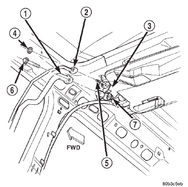 Fig. 51 Rear Overhead A/C Unit Refrigerant Line Remove/Install
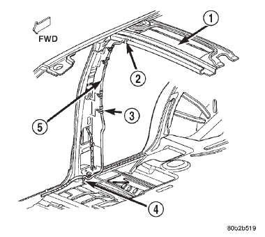 Fig. 52 Rear Overhead A/C Drain Hose Remove/ Install
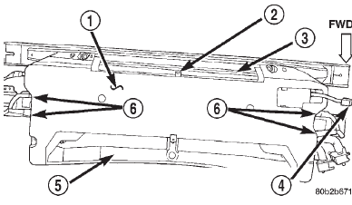 Fig. 53 Rear Overhead A/C Unit Lower Housing Cover Remove/Install
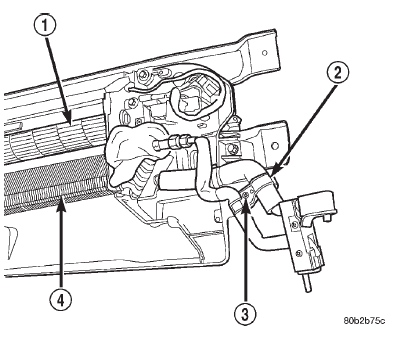 Fig. 54 Rear A/C Tube Retaining Strap Remove/ Install
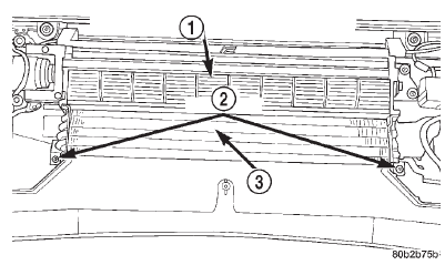 Fig. 55 Rear Evaporator Coil Remove/Install
Dodge Durango (DN) 1998-2003 Service Manual
- Lubrication and Maintenance
- Suspension
- Differential and Driveline
- Brakes
- Cooling System
- Battery
- Starting Systems
- Charging System
- Ignition System
- Instrument Panel Systems
- Audio Systems
- Horn Systems
- Speed Control System
- Turn Signal and Hazard Warning Systems
- Wiper and Washer Systems
- Lamps
- Passive Restraint Systems
- Electrically Heated Systems
- Power Distribution System
- Power Lock Systems
- Vehicle Theft/Security Systems
- Power Seat System
- Power Window Systems
- Power Mirror Systems
- Chime/Buzzer Warning Systems
- Overhead Console Systems
- Engine
- Exhaust System
- Frame and Bumpers
- Fuel System
- Steering
- Transmission and Transfer Case
- Tires and Wheels
- Body
- Heating and Air Conditioning
- Emission Control Systems
- Introduction
Categories
