Diagnosis and testing
WARNING: ON VEHICLES EQUIPPED WITH AIRBAGS,
REFER TO GROUP 8M - PASSIVE
RESTRAINT SYSTEMS BEFORE ATTEMPTING ANY
STEERING WHEEL, STEERING COLUMN, OR
INSTRUMENT PANEL COMPONENT DIAGNOSIS OR
SERVICE. FAILURE TO TAKE THE PROPER PRECAUTIONS
COULD RESULT IN ACCIDENTAL AIRBAG
DEPLOYMENT AND POSSIBLE PERSONAL
INJURY. The Vehicle Theft Security System (VTSS) and the
Chrysler Collision Detection (CCD) data bus network
should be diagnosed using a DRB scan tool and the
proper Diagnostic Procedures manual. The DRB will
provide confirmation that the data bus is functional,
that the high-line Central Timer Module (CTM) is
receiving and sending the proper messages on the
data bus, that the CTM is receiving the proper hardwired
inputs and sending the proper hard-wired outputs,
and that the Powertrain Control Module (PCM)
is receiving the data bus messages from the CTM.
Refer to the Vehicle Theft Security System menu
item on the DRB scan tool for the procedures. Refer
to 8W-39 - Vehicle Theft Security System in Group
8W - Wiring Diagrams for complete circuit descriptions
and diagrams. Refer to Vehicle Theft Security System in the
index of this service manual for the location of complete
door lock cylinder switch wiring diagrams.
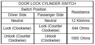
(1) Disconnect the door lock cylinder switch wire
harness connector from the door wire harness connector.
(2) Using an ohmmeter, perform the switch resistance
checks between the two cavities of the door
lock cylinder switch wire harness connector. Actuate
the switch by rotating the key in the door lock cylinder
to test for the proper resistance values in each of
the three switch positions, as shown in the Door Lock
Cylinder Switch chart. (3) If a door lock cylinder switch fails any of the
resistance tests, replace the faulty switch as
required. Refer to Vehicle Theft Security System in the
index of this service manual for the location of complete
liftgate lock cylinder switch wiring diagrams.
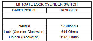
(1) Disconnect the likftgate lock cylinder switch
wire harness connector from the liftgate wire harness
connector. (2) Using an ohmmeter, perform the switch resistance
checks between the two cavities of the liftgate
lock cylinder switch wire harness connector. Actuate
the switch by rotating the key in the liftgate lock cylinder
to test for the proper resistance values in each
of the three switch positions, as shown in the Liftgate
Lock Cylinder Switch chart. (3) If a liftgate lock cylinder switch fails any of the
resistance tests, replace the faulty switch as
required. The headlamp (or security) and horn relays are
located in the Power Distribution Center (PDC) in
the engine compartment. Each of these relays can be
tested as described in the following procedure, however
the circuits they are used in do vary. To test the
relay circuits, refer to the circuit descriptions and
diagrams in 8W-39 - Vehicle Theft Security System
in Group 8W - Wiring Diagrams. WARNING: ON VEHICLES EQUIPPED WITH AIRBAGS,
REFER TO GROUP 8M - PASSIVE
RESTRAINT SYSTEMS BEFORE ATTEMPTING ANY
STEERING WHEEL, STEERING COLUMN, OR
INSTRUMENT PANEL COMPONENT DIAGNOSIS OR
SERVICE. FAILURE TO TAKE THE PROPER PRECAUTIONS
COULD RESULT IN ACCIDENTAL AIRBAG
DEPLOYMENT AND POSSIBLE PERSONAL
INJURY. Remove the relay (Fig. 1) from the PDC as
described in this group to perform the following tests:
(1) A relay in the de-energized position should
have continuity between terminals 87A and 30, and
no continuity between terminals 87 and 30. If OK, go
to Step 2. If not OK, replace the faulty relay.
(2) Resistance between terminals 85 and 86 (electromagnet)
should be 75 6 5 ohms. If OK, go to Step
3. If not OK, replace the faulty relay.
(3) Connect a battery to terminals 85 and 86.
There should now be continuity between terminals
30 and 87, and no continuity between terminals 87A
and 30. If OK, test the relay circuits. If not OK,
replace the faulty relay.
Vehicle theft security system
Door lock cylinder switch
Liftgate lock cylinder switch
Relays
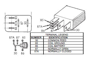 Fig. 1 Relay Terminals
Dodge Durango (DN) 1998-2003 Service Manual
- Lubrication and Maintenance
- Suspension
- Differential and Driveline
- Brakes
- Cooling System
- Battery
- Starting Systems
- Charging System
- Ignition System
- Instrument Panel Systems
- Audio Systems
- Horn Systems
- Speed Control System
- Turn Signal and Hazard Warning Systems
- Wiper and Washer Systems
- Lamps
- Passive Restraint Systems
- Electrically Heated Systems
- Power Distribution System
- Power Lock Systems
- Vehicle Theft/Security Systems
- Power Seat System
- Power Window Systems
- Power Mirror Systems
- Chime/Buzzer Warning Systems
- Overhead Console Systems
- Engine
- Exhaust System
- Frame and Bumpers
- Fuel System
- Steering
- Transmission and Transfer Case
- Tires and Wheels
- Body
- Heating and Air Conditioning
- Emission Control Systems
- Introduction
Categories
