Description and operation
DESCRIPTION The antilock brake system (ABS) is an electronically
operated, all wheel brake control system.
The system is designed to prevent wheel lockup
and maintain steering control during periods of high
wheel slip when braking. Preventing lockup is accomplished
by modulating fluid pressure to the wheel
brake units.
The hydraulic system is a three channel design.
The front wheel brakes are controlled individually
and the rear wheel brakes in tandem (Fig. 1). The
ABS electrical system is separate from other electrical
circuits in the vehicle. A specially programmed
controller antilock brake unit operates the system
components.
ABS system major components include: OPERATION Battery voltage is supplied to the CAB ignition terminal
when the ignition switch is turned to Run position.
The CAB performs a system initialization
procedure at this point. Initialization consists of a
static and dynamic self check of system electrical
components.
The static and dynamic checks occurs at ignition
start up. During the dynamic check, the CAB briefly
cycles the pump and solenoids to verify operation. An
audible noise may be heard during this self check.
This noise should be considered normal.
1 - MASTER CYLINDER AND RESERVOIR 2 - POWER BRAKE BOOSTER 3 - WIRES TO WHEEL SPEED SENSORS 4 - RIGHT REAR WHEEL 5 - LEFT REAR WHEEL 6 - HYDRAULIC BRAKE LINES TO WHEELS 7 - COMBINATION VALVE 8 - HARNESS 9 - RIGHT FRONT WHEEL 10 - LEFT FRONT WHEEL 11 - CAB/HCU If an ABS component exhibits a fault during initialization,
the CAB illuminates the amber warning
light and registers a fault code in the microprocessor
memory.
The CAB monitors wheel speed sensor inputs continuously
while the vehicle is in motion. However,
the CAB will not activate any ABS components as
long as sensor inputs indicate normal braking. During normal braking, the master cylinder, power
booster and wheel brake units all function as they
would in a vehicle without ABS. The HCU components
are not activated.
The purpose of the antilock system is to prevent
wheel lockup during periods of high wheel slip. Preventing
lockup helps maintain vehicle braking action
and steering control.
The antilock CAB activates the system whenever
sensor signals indicate periods of high wheel slip.
High wheel slip can be described as the point where
wheel rotation begins approaching 20 to 30 percent of
actual vehicle speed during braking. Periods of high
wheel slip occur when brake stops involve high pedal
pressure and rate of vehicle deceleration.
The antilock system prevents lockup during high
slip conditions by modulating fluid apply pressure to
the wheel brake units.
Brake fluid apply pressure is modulated according
to wheel speed, degree of slip and rate of deceleration.
Sensors at each front wheel convert wheel speed
into electrical signals. These signals are transmitted
to the CAB for processing and determination of
wheel slip and deceleration rate.
The ABS system has three fluid pressure control
channels. The front brakes are controlled separately
and the rear brakes in tandem. A speed sensor input
signal indicating a high slip condition activates the
CAB antilock program.
Two solenoid valves are used in each antilock control
channel. The valves are all located within the
HCU valve body and work in pairs to either increase,
hold, or decrease apply pressure as needed in the
individual control channels.
The solenoid valves are not static during antilock
braking. They are cycled continuously to modulate
pressure. Solenoid cycle time in antilock mode can be
measured in milliseconds. DESCRIPTION The CAB is mounted on the top of the hydraulic
control unit (Fig. 2). The CAB operates the ABS system
and is separate from other vehicle electrical circuits.
CAB voltage source is through the ignition
switch in the RUN position. OPERATION The CAB contains dual microprocessors. A logic
block in each microprocessor receives identical sensor
signals. These signals are processed and compared
simultaneously.
The CAB contains a self check program that illuminates
the ABS warning light when a system fault is detected. Faults are stored
in a diagnostic program
memory and are accessible with the DRB scan tool.
ABS faults remain in memory until cleared, or
until after the vehicle is started approximately 50
times. Stored faults are not erased if the battery is
disconnected. NOTE: If the CAB needs to be replaced, the rear
axle type and tire revolutions per mile must be programed
into the new CAB. For axle type refer to
Group 3 Differential and Driveline. For tire revolutions
per mile refer to Group 22 Tire and Wheels. To
program the CAB refer to the Chassis Diagnostic
Manual.
1 - CAB 2 - PUMP WIRING 3 - PUMP MOTOR 4 - HCU DESCRIPTION The hydraulic control unit (HCU) consists of a
valve body, pump, two accumulators and a motor
(Fig. 2). The assembly is mounted on the driverside
inner fender under the hood. OPERATION The pump, motor, and accumulators are combined
into an assembly attached to the valve body. The
accumulators store the extra fluid which had to be
dumped from the brakes. This is done to prevent the
wheels from locking up. The pump provides the fluid
volume needed and is operated by a DC type motor.
The motor is controlled by the CAB. During normal braking, the HCU solenoid valves
and pump are not activated. The master cylinder and
power booster operate the same as a vehicle without
an ABS brake system.
The valve body contains the solenoid valves. The
valves modulate brake pressure during antilock braking
and are controlled by the CAB.
The HCU provides three channel pressure control
to the front and rear brakes. One channel controls
the rear wheel brakes in tandem. The two remaining
channels control the front wheel brakes individually.
During antilock braking, the solenoid valves are
opened and closed as needed. The valves are not
static. They are cycled rapidly and continuously to
modulate pressure and control wheel slip and deceleration.
During antilock braking, solenoid valve pressure
modulation occurs in three stages, pressure decrease,
pressure hold, and pressure increase. The valves are
all contained in the valve body portion of the HCU. PRESSURE DECREASE The inlet valve is closed and the outlet valve is
opened during the pressure decrease cycle.
A pressure decrease cycle is initiated when speed
sensor signals indicate high wheel slip at one or
more wheels. At this point, the CAB closes the inlet
to prevent the driver from further increasing the
brake pressure and locking the brakes. The CAB
then opens the outlet valve, which also opens the
return circuit to the accumulators. Fluid pressure is
allowed to bleed off (decrease) as needed to prevent
wheel lock.
Once the period of high wheel slip has ended, the
CAB closes the outlet valve and begins a pressure
increase or hold cycle as needed. PRESSURE HOLD Both solenoid valves are closed in the pressure
hold cycle. Fluid apply pressure in the control channel
is maintained at a constant rate. The CAB maintains
the hold cycle until sensor inputs indicate a
pressure change is necessary. PRESSURE INCREASE The inlet valve is open and the outlet valve is
closed during the pressure increase cycle. The pressure
increase cycle is used to counteract unequal
wheel speeds. This cycle controls re-application of
fluid apply pressure due to changing road surfaces or
wheel speed. DESCRIPTION The ABS brake system uses 3 wheel speed sensors.
A sensor is mounted to each front steering knuckles.
The third sensor is mounted on top of the rear axle
differential housing. OPERATION The WSS consists of a magnet surrounded by
windings from a single strand of wire. The sensor
sends a small AC signal to the CAB. This signal is
generated by magnetic induction. The magnetic
induction is created when a toothed sensor ring
(exciter ring or tone wheel) passes the stationary
magnetic WSS.
When the ring gear is rotated, the exciter ring
passes the tip of the WSS. As the exciter ring tooth
approaches the tip of the WSS, the magnetic lines of
force expand, causing the magnetic field to cut across
the sensor's windings. This, in turn causes current to
flow through the WSS circuit (Fig. 3) in one direction.
When the exciter ring tooth moves away from
the sensor tip, the magnetic lines of force collapse
cutting the winding in the opposite direction. This
causes the current to flow in the opposite direction.
Every time a tooth of the exciter ring passes the tip
of the WSS, an AC signal is generated. Each AC signal
(positive to negative signal or sinewave) is interpreted
by the CAB. It then compares the frequency of
the sinewave to a time value to calculate vehicle
speed. The CAB continues to monitor the frequency
to determine a deceleration rate that would indicate
a possible wheel-locking tendency.
The signal strength of any magnetic induction sensor
is directly affected by: The rear WSS is not adjustable. A clearance specification
has been established for manufacturing tolerances.
If the clearance is not within these
specifications, then either the WSS or other components
may be damaged. The clearance between the
WSS and the exciter ring is 0.005 - 0.050 in.
1 - MAGNETIC CORE 2 - CAB 3 - AIR GAP 4 - EXCITER RING 5 - COIL The assembly plant performs a "Rolls Test" on
every vehicle that leaves the assembly plant. One of
the test performed is a test of the WSS. To properly
test the sensor, the assembly plant connects test
equipment to the Data Link Connector (DLC). This
connector is located to the right of the steering column
and attached to the lower portion of the instrument
panel (Fig. 4). The rolls test terminal is spliced
to the WSS circuit. The vehicle is then driven on a
set of rollers and the WSS output is monitored for
proper operation. DESCRIPTION The amber ABS warning lamp and red warning
lamp are located in the instrument cluster. The
amber ABS warning lamp illuminates at start-up to
perform a self check. The lamp goes out when the
self check program determines the system is operating
normal. The red brake warning lamp is used to
alert the driver of a hydraulic fault or that the parking
brake is applied.
1 - 16-WAY DATA LINK CONNECTOR OPERATION If an ABS component exhibits a fault the CAB will
illuminate the ABS warning lamp and register a
trouble code in the microprocessor. The lamp is controlled
by the CAB. The CAB controls the lamp sending
a message to the instrument cluster.
If red warning lamp is illuminate with the amber
warning lamp, this may indicate a electronic brake
distribution fault.
The red warning lamp will illuminate if an ABS
component exhibits a fault and the amber lamp is
burned out.Antilock brake system
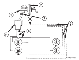 Fig. 1 Antilock Brake System
Controller antilock brakes
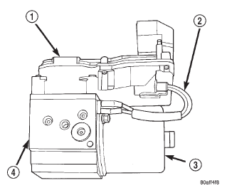 Fig. 2 CAB/HCU
Hydraulic control unit
Wheel speed sensor
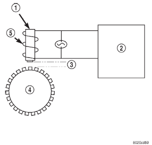 Fig. 3 Operation of the Wheel Speed Sensor
Abs warning lamp
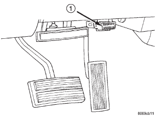 Fig. 4 Data Link Connector - Typical
Dodge Durango (DN) 1998-2003 Service Manual
- Lubrication and Maintenance
- Suspension
- Differential and Driveline
- Brakes
- Cooling System
- Battery
- Starting Systems
- Charging System
- Ignition System
- Instrument Panel Systems
- Audio Systems
- Horn Systems
- Speed Control System
- Turn Signal and Hazard Warning Systems
- Wiper and Washer Systems
- Lamps
- Passive Restraint Systems
- Electrically Heated Systems
- Power Distribution System
- Power Lock Systems
- Vehicle Theft/Security Systems
- Power Seat System
- Power Window Systems
- Power Mirror Systems
- Chime/Buzzer Warning Systems
- Overhead Console Systems
- Engine
- Exhaust System
- Frame and Bumpers
- Fuel System
- Steering
- Transmission and Transfer Case
- Tires and Wheels
- Body
- Heating and Air Conditioning
- Emission Control Systems
- Introduction
Categories
