Transmission
DISASSEMBLY
(1) Clean transmission exterior with steam gun or with solvent. Wear eye protection during cleaning operations.
(2) Place transmission in a vertical position.
(3) Measure and record input shaft end play readings.
(4) Remove shift and throttle levers from valve body manual lever shaft.
(5) Place transmission in horizontal position.
(6) Remove transmission oil pan and gasket.
(7) Remove filter from valve body (Fig. 148). Keep filter screws separate from other valve body screws.
Filter screws are longer and should be kept with filter.
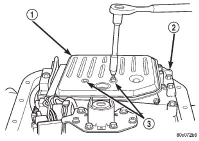 Fig. 148 Oil Filter Removal
1 - OIL FILTER
2 - VALVE BODY
3 - FILTER SCREWS (2)
(8) Remove park/neutral position switch.
(9) Remove hex head bolts attaching valve body to transmission case (Fig. 149). A total of 10 bolts are used. Note different bolt lengths for assembly reference.
(10) Remove valve body assembly. Push valve body harness connector out of case. Then work park rod and valve body out of case (Fig. 150).
(11) Remove accumulator piston and inner and outer springs (Fig. 151).
(12) Remove pump oil seal with suitable pry tool or slide-hammer mounted screw.
(13) Loosen front band adjusting screw locknut 4-5 turns. Then tighten band adjusting screw until band is tight around front clutch retainer. This prevents front/rear clutches from coming out with pump and possibly damaging clutch or pump components.
(14) Remove oil pump bolts.
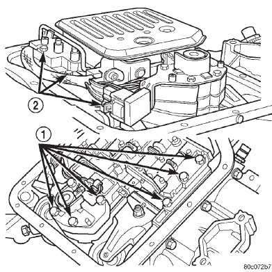 Fig. 149 Valve Body Bolt Locations
1 - VALVE BODY BOLTS
2 - VALVE BODY BOLTS
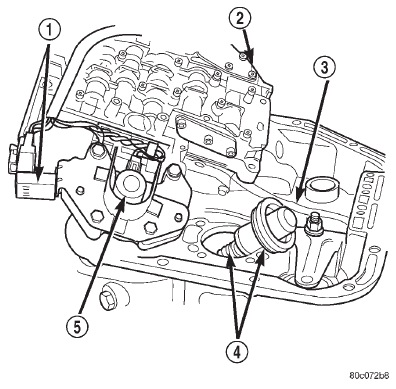 Fig. 150 Valve Body Removal
1 - GOVERNOR PRESSURE SENSOR
2 - VALVE BODY
3 - PARK ROD
4 - ACCUMULATOR PISTON
5 - GOVERNOR PRESSURE SOLENOID
(15) Thread bolts of Slide Hammer Tools C-3752 into threaded holes in pump body flange (Fig. 152).
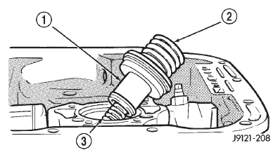 Fig. 151 Accumulator Piston And Springs
1 - ACCUMULATOR PISTON
2 - OUTER SPRING
3 - INNER SPRING
(16) Bump slide hammer weights outward to remove pump and reaction shaft support assembly from case (Fig. 152).
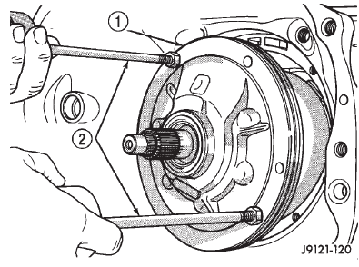 Fig. 152 Removing Oil Pump And Reaction Shaft Support Assembly
1 - OIL PUMP AND REACTION SHAFT SUPPORT ASSEMBLY
2 - SLIDE HAMMER TOOLS C-3752
(17) Loosen front band adjusting screw until band is completely loose.
(18) Squeeze front band together and remove band strut (Fig. 153).
(19) Remove front band lever (Fig. 154).
(20) Remove front band lever shaft plug, if necessary, from converter housing.
(21) Remove front band lever shaft.
(22) Remove front and rear clutch units as assembly.
Grasp input shaft, hold clutch units together and remove them from case (Fig. 155).
(23) Lift front clutch off rear clutch (Fig. 156). Set clutch units aside for overhaul.
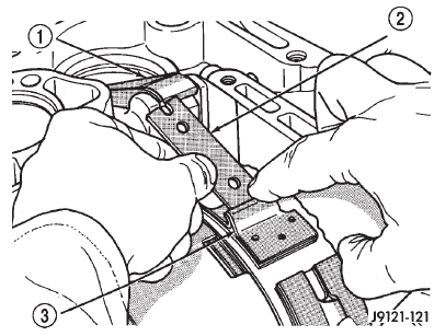 Fig. 153 Removing/Installing Front Band Strut
1 - BAND LEVER
2 - BAND STRUT
3 - FRONT BAND
 Fig. 154 Removing/Installing Front Band Lever
1 - FRONT BAND LEVER
(24) Remove intermediate shaft thrust washer from front end of shaft or from rear clutch hub (Fig.
157).
(25) Remove output shaft thrust plate from intermediate shaft hub (Fig. 158).
(26) Slide front band off driving shell (Fig. 159) and remove band from case.
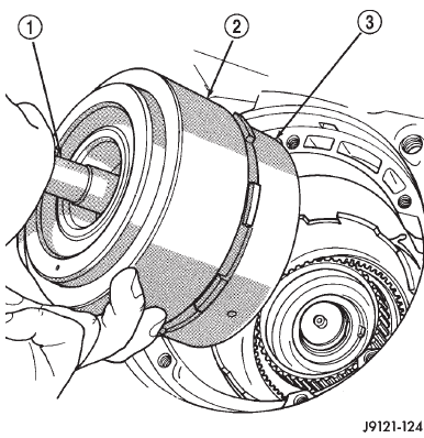 Fig. 155 Removing Front/Rear Clutch Assemblies
1 - INPUT SHAFT
2 - FRONT CLUTCH
3 - REAR CLUTCH
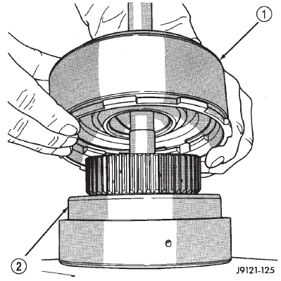 Fig. 156 Separating Front/Rear Clutch Assemblies
1 - FRONT CLUTCH
2 - REAR CLUTCH
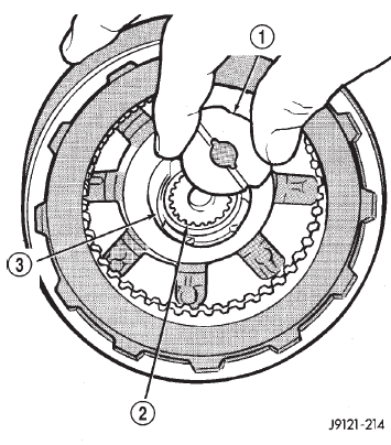 Fig. 157 Removing Intermediate Shaft Thrust Washer
1 - INTERMEDIATE SHAFT THRUST WASHER
2 - INPUT SHAFT
3 - REAR CLUTCH RETAINER HUB
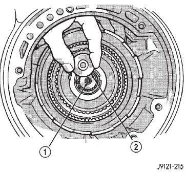 Fig. 158 Removing Intermediate Shaft Thrust Plate
1 - INTERMEDIATE SHAFT HUB
2 - INTERMEDIATE SHAFT THRUST PLATE
 Fig. 159 Front Band Removal/Installation
1 - DRIVING SHELL
2 - FRONT BAND
(27) Remove planetary geartrain as assembly (Fig.
160). Support geartrain with both hands during removal. Do not allow machined surfaces on intermediate shaft or overdrive piston retainer to become nicked or scratched.
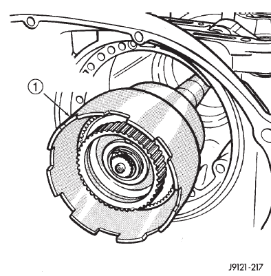 Fig. 160 Removing Planetary Geartrain And Intermediate Shaft Assembly
1 - PLANETARY GEARTRAIN AND INTERMEDIATE SHAFT ASSEMBLY
(28) If overdrive unit is not to be serviced, install Alignment Shaft 6227-2 into the overdrive unit to prevent misalignment of the overdrive clutches during service of main transmission components.
(29) Loosen rear band adjusting screw 4-5 turns.
(30) Remove low-reverse drum snap ring (Fig.
161).
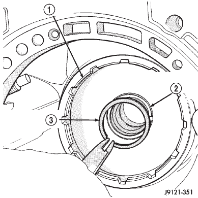 Fig. 161 Removing Low-Reverse Drum Snap Ring
1 - LOW-REVERSE DRUM
2 - HUB OF OVERDRIVE PISTON RETAINER
3 - LOW-REVERSE DRUM SNAP RING
(31) Remove low-reverse drum and reverse band.
(32) Remove overrunning clutch roller and spring assembly as a unit (Fig. 162).
(33) Compress front servo rod guide about 1/8 inch with Valve Spring Compressor C-3422-B (Fig. 163).
(34) Remove front servo rod guide snap ring.
Exercise caution when removing snap ring.
Servo bore can be scratched or nicked if care is not exercised.
(35) Remove compressor tools and remove front servo rod guide, spring and servo piston.
(36) Compress rear servo spring retainer about 1/16 inch with Valve Spring Compressor C-3422-B (Fig. 164).
(37) Remove rear servo spring retainer snap ring.
Then remove compressor tools and remove rear servo spring and piston.
(38) Inspect transmission components.
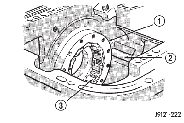 Fig. 162 Overrunning Clutch Assembly Removal
1 - OVERRUNNING CLUTCH CAM
2 - REAR BAND REACTION PIN
3 - OVERRUNNING CLUTCH ASSEMBLY
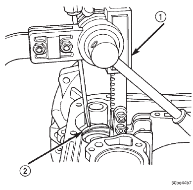 Fig. 163 Compressing Front Servo Rod Guide
1 - SPRING COMPRESSOR TOOL C-3422-B
2 - ROD GUIDE SNAP RING
NOTE: TO SERVICE THE OVERRUNNING CLUTCH CAM OR OVERDRIVE PISTON RETAINER, REFER TO OVERRUNNING CLUTCH CAM SERVICE IN THIS SECTION.
ASSEMBLY
Do not allow dirt, grease, or foreign material to enter the case or transmission components during assembly. Keep the transmission case and components clean. Also make sure the tools and workbench area used for assembly operations are equally clean.
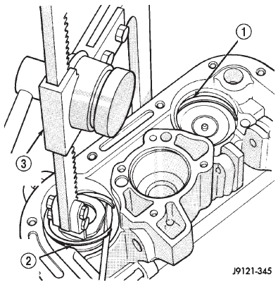 Fig. 164 Compressing Rear Servo Spring
1 - FRONT SERVO SNAP RING
2 - REAR SERVO SNAP RING
3 - SPECIAL TOOL
Shop towels used for wiping off tools and hands must be made from lint free material. Lint will stick to transmission parts and could interfere with valve operation, or even restrict fluid passages.
Lubricate the transmission components with Mopart transmission fluid during reassembly. Use Mopart Door Ease, or Ru-Glyde on seals and O-rings to ease installation.
Petroleum jelly can also be used to hold thrust washers, thrust plates and gaskets in position during assembly. However, do not use chassis grease, bearing grease, white grease, or similar lubricants on any transmission part. These types of lubricants can eventually block or restrict fluid passages and interfere with valve operation. Use petroleum jelly only.
Do not force parts into place. The transmission components and subassemblies are easily installed by hand when properly aligned.
If a part seems extremely difficult to install, it is either misaligned or incorrectly assembled. Also verify that thrust washers, thrust plates and seal rings are correctly positioned before assembly. These parts can interfere with proper assembly if mis-positioned.
The planetary geartrain, front/rear clutch assemblies and oil pump are all much easier to install when the transmission case is upright.
(1) Install rear servo piston, spring and retainer (Fig. 165). Install spring on top of servo piston and install retainer on top of spring.
(2) Install front servo piston assembly, servo spring and rod guide (Fig. 166).
(3) Compress front/rear servo springs with Valve Spring Compressor C-3422-B and install each servo snap ring (Fig. 167).
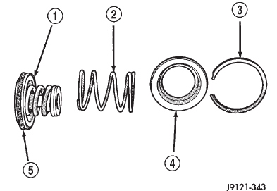 Fig. 165 Rear Servo Components
1 - SERVO PISTON
2 - PISTON SPRING
3 - SNAP RING
4 - RETAINER
5 - PISTON SEAL
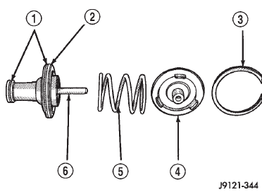 Fig. 166 Front Servo Components
1 - PISTON SEAL RINGS
2 - SERVO PISTON
3 - SNAP RING
4 - ROD GUIDE
5 - SPRING
6 - ROD
(4) Lubricate clutch cam rollers with transmission fluid.
(5) Install rear band in case (Fig. 168). Be sure twin lugs on band are seated against reaction pin.
(6) Install low-reverse drum and check overrunning clutch operation as follows:
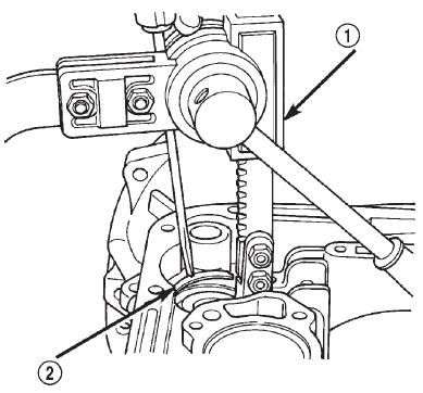 Fig. 167 Compressing Front/Rear Servo Springs
1 - SPRING COMPRESSOR TOOL C-3422-B
2 - ROD GUIDE SNAP RING
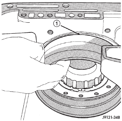 Fig. 168 Rear Band Installation
1 - REAR BAND
(a) Lubricate overrunning clutch race (on drum hub) with transmission fluid.
(b) Guide drum through rear band.
(c) Tilt drum slightly and start race (on drum hub) into overrunning clutch rollers.
(d) Press drum rearward and turn it in clockwise direction until drum seats in overrunning clutch (Fig. 169).
(e) Turn drum back and forth. Drum should rotate freely in clockwise direction and lock in counterclockwise direction (as viewed from front of case).
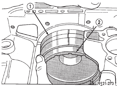 Fig. 169 Installing Low-Reverse Drum
1 - REAR BAND
2 - LOW-REVERSE DRUM
(7) Install snap ring that secures low-reverse drum to hub of overdrive piston retainer (Fig. 170).
(8) Install rear band lever and pivot pin (Fig. 171).
Align lever with pin bores in case and push pivot pin into place.
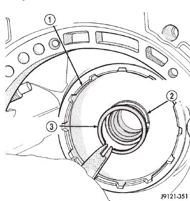 Fig. 170 Installing Low-Reverse Drum Retaining Snap Ring
1 - LOW-REVERSE DRUM
2 - HUB OF OVERDRIVE PISTON RETAINER
3 - LOW-REVERSE DRUM SNAP RING
(9) Install planetary geartrain assembly (Fig. 172).
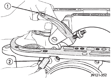 Fig. 171 Rear Band Lever And Pivot Pin Installation
1 - REAR BAND LEVER
2 - LEVER PIVOT PIN
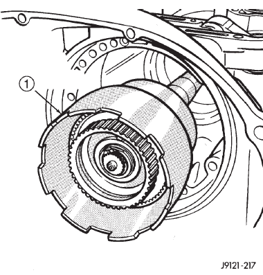 Fig. 172 Installing Planetary Geartrain
1 - PLANETARY GEARTRAIN AND INTERMEDIATE SHAFT ASSEMBLY
(10) Install thrust plate on intermediate shaft hub (Fig. 173). Use petroleum jelly to hold thrust plate in place.
(11) Check seal ring on rear clutch retainer hub and seal rings on input shaft (Fig. 174). Also verify that shaft seal rings are installed in sequence shown.
(12) Install rear clutch thrust washer (Fig. 175).
Use additional petroleum jelly to hold washer in place if necessary.
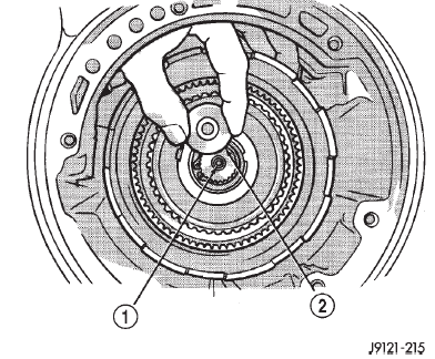 Fig. 173 Installing Intermediate Shaft Thrust Plate
1 - INTERMEDIATE SHAFT HUB
2 - INTERMEDIATE SHAFT THRUST PLATE
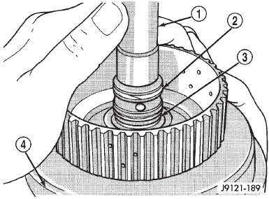 Fig. 174 Input Shaft Seal Ring Location
1 - INPUT SHAFT
2 - TEFLON SEAL RING
3 - METAL SEAL RING
4 - REAR CLUTCH RETAINER
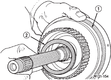 Fig. 175 Installing Rear Clutch Thrust Washer
1 - REAR CLUTCH RETAINER
2 - REAR CLUTCH THRUST WASHER (FIBER)
(13) Align clutch discs in front clutch and install front clutch on rear clutch (Fig. 176). Rotate front clutch retainer back and forth until completely seated on rear clutch retainer.
(14) Coat intermediate shaft thrust washer with petroleum jelly. Then install washer in rear clutch hub (Fig. 177). Use enough petroleum jelly to hold washer in place. Be sure grooved side of washer faces rearward (toward output shaft) as shown.
Also note that washer only fits one way in clutch hub. Note thickness of this washer. It is a select fit part and is used to control transmission end play.
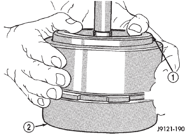 Fig. 176 Assembling Front And Rear Clutch Units
1 - TURN FRONT CLUTCH BACK & FORTH UNTIL SEATED
2 - REAR CLUTCH ASSEMBLY
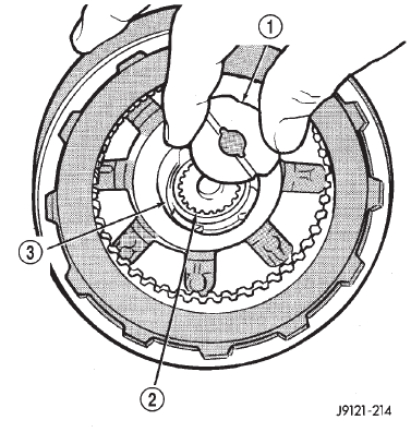 Fig. 177 Installing Intermediate Shaft Thrust Plate
1 - INTERMEDIATE SHAFT THRUST WASHER
2 - INPUT SHAFT
3 - REAR CLUTCH RETAINER HUB
(15) Align drive teeth on rear clutch discs with small screwdriver (Fig. 178). This makes installation on front planetary easier.
(16) Raise front end of transmission upward as far as possible and support case with wood blocks. Front/ rear clutch and oil pump assemblies are easier to install if transmission is as close to upright position as possible.
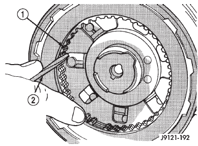 Fig. 178 Aligning Rear Clutch Disc Lugs
1 - REAR CLUTCH DISCS
2 - USE SMALL SCREWDRIVER TO ALIGN CLUTCH DISC TEETH
(17) Slide front band into case.
(18) Install front and rear clutch units as assembly (Fig. 179). Align rear clutch with front annulus gear and install assembly in driving shell. Be sure output shaft thrust washer and thrust plate are not displaced during installation.
(19) Carefully work assembled clutches back and forth to engage and seat rear clutch discs on front annulus gear. Also be sure front clutch drive lugs are fully engaged in slots of driving shell after installation.
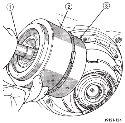 Fig. 179 Installing Front/Rear Clutch Assemblies
1 - INPUT SHAFT
2 - FRONT CLUTCH
3 - REAR CLUTCH
(20) Assemble front band strut.
(21) Install front band adjuster, strut and adjusting screw (Fig. 180).
(22) Tighten band adjusting screw until band just grips clutch retainer. Verify that front/rear clutches are still seated before continuing.
(23) Check seal rings on reaction shaft support hub. Verify that seal rings are hooked together and that front clutch thrust washer is properly positioned (Fig. 181). Use petroleum jelly to hold thrust washer in place if necessary.
(24) Lubricate oil pump body seal with petroleum jelly. Lubricate pump shaft seal lip with petroleum jelly.
(25) Thread two Pilot Stud Tools C-3288-B into bolt holes in oil pump bore flange (Fig. 182).
(26) Align and install oil pump gasket (Fig. 182).
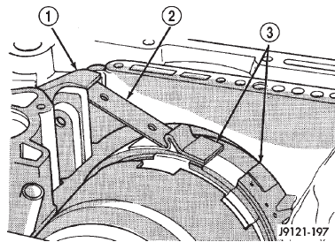 Fig. 180 Front Band Linkage Installation
1 - BAND LEVER
2 - BAND STRUT
3 - FRONT BAND
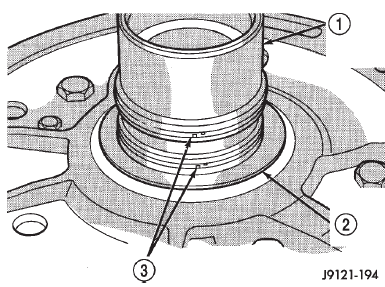 Fig. 181 Reaction Shaft Support Seal Rings And Front Clutch Thrust Washer
1 - REACTION SHAFT SUPPORT HUB
2 - FRONT CLUTCH THRUST WASHER
3 - SEAL RINGS
(27) Install oil pump (Fig. 183). Align and position pump on pilot studs. Slide pump down studs and work it into front clutch hub and case by hand. Then install 2 or 3 pump bolts to hold pump in place.
(28) Remove pilot stud tools and install remaining oil pump bolts. Tighten bolts alternately in diagonal pattern to 20 N*m (15 ft. lbs.).
(29) Measure input shaft end play (Fig. 184).
NOTE: If end play is incorrect, transmission is incorrectly assembled, or the intermediate shaft thrust washer is incorrect. The intermediate shaft thrust washer is selective.
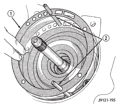 Fig. 182 Installing Pilot Studs And Oil Pump Gasket
1 - OIL PUMP GASKET
2 - PILOT STUD TOOLS C-3288-B
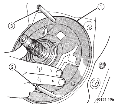 Fig. 183 Installing Oil Pump Assembly In Case
1 - OIL PUMP
2 - PILOT STUD TOOL
3 - PILOT STUD TOOL
(a) Attach Adapter 8266-6 to Handle 8266-8.
(b) Attach dial indicator C-3339 to Handle 8266-8.
(c) Install the assembled tool onto the input shaft of the transmission and tighten the retaining screw on Adapter 8266-6 to secure it to the input shaft.
(d) Position the dial indicator plunger against a flat spot on the oil pump and zero the dial indicator.
(e) Move input shaft in and out and record reading.
End play should be 0.56 - 2.31 mm (0.022 - 0.091 in.). Adjust as necessary.
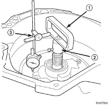 Fig. 184 Checking Input Shaft End Play
1 - TOOL 8266-8
2 - TOOL 8266-6
3 - TOOL C-3339
(30) Install accumulator piston and inner and outer springs (Fig. 185).
(31) Verify that valve body solenoid harness is secured in 3-4 accumulator housing cover plate.
(32) Install valve body as follows: (a) Align and carefully insert park rod into pawl.
Rod will make click noise as it enters pawl. Move rod slightly to check engagement.
(b) Align and seat valve body on case. Be sure manual lever shaft and overdrive connector are fully seated in case. Also be sure valve body wiring is not pinched or kinked.
(c) Install and start all valve body attaching bolts by hand. Then tighten bolts evenly, in a diagonal pattern to 12 N*m (105 in. lbs.) torque. Do not overtighten valve body bolts. This could result in distortion and cross leakage after installation..
CAUTION: It is possible for the park rod to displace into a cavity just above the pawl sprag during installation. Make sure the rod is actually engaged in the pawl and has not displaced into the cavity.
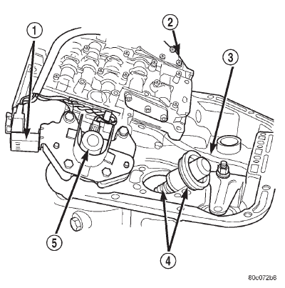 Fig. 185 Accumulator Piston And Springs
1 - GOVERNOR PRESSURE SENSOR
2 - VALVE BODY
3 - PARK ROD
4 - ACCUMULATOR PISTON
5 - GOVERNOR PRESSURE SOLENOID
(33) Install new filter on valve body. Tighten filter screws to 4 N*m (35 in. lbs.).
(34) Adjust front and rear bands.
(35) Install seal on park/neutral position switch.
Then install and tighten switch to 34 N*m (25 ft.
lbs.).
(36) Install magnet in oil pan. Magnet goes on small protrusion at corner of pan.
(37) Position new oil pan gasket on case and install oil pan. Tighten pan bolts to 17 N*m (13 ft.
lbs.).
(38) Install new valve body manual shaft seal in case (Fig. 186). Lubricate seal lip and manual shaft with petroleum jelly. Start seal over shaft and into case. Seat seal with 15/16 inch, deep well socket.
(39) Install throttle valve and shift selector levers on valve body manual lever shaft.
Dodge Durango (DN) 1998-2003 Service Manual
- Lubrication and Maintenance
- Suspension
- Differential and Driveline
- Brakes
- Cooling System
- Battery
- Starting Systems
- Charging System
- Ignition System
- Instrument Panel Systems
- Audio Systems
- Horn Systems
- Speed Control System
- Turn Signal and Hazard Warning Systems
- Wiper and Washer Systems
- Lamps
- Passive Restraint Systems
- Electrically Heated Systems
- Power Distribution System
- Power Lock Systems
- Vehicle Theft/Security Systems
- Power Seat System
- Power Window Systems
- Power Mirror Systems
- Chime/Buzzer Warning Systems
- Overhead Console Systems
- Engine
- Exhaust System
- Frame and Bumpers
- Fuel System
- Steering
- Transmission and Transfer Case
- Tires and Wheels
- Body
- Heating and Air Conditioning
- Emission Control Systems
- Introduction
Categories
