Schematics and diagrams
Hydraulic schematics
 HYDRAULIC FLOW IN PARK
 HYDRAULIC FLOW IN NEUTRAL
 HYDRAULIC FLOW IN REVERSE
 HYDRAULIC FLOW IN DRIVE FIRST GEAR
 HYDRAULIC FLOW IN DRIVE SECOND GEAR
 HYDRAULIC FLOW IN DRIVE THIRD GEAR (CONVERTER CLUTCH NOT APPLIED)
 HYDRAULIC FLOW IN DRIVE THIRD GEAR (CONVERTER CLUTCH APPLIED)
 HYDRAULIC FLOW IN DRIVE FOURTH GEAR (CONVERTER CLUTCH NOT APPLIED)
 HYDRAULIC FLOW IN DRIVE FOURTH GEAR (CONVERTER CLUTCH APPLIED)
 HYDRAULIC FLOW IN MANUAL LOW (1)
 HYDRAULIC FLOW IN MANUAL SECOND (2)
 HYDRAULIC FLOW DURING FULL THROTTLE 3-2 DOWNSHIFT (PASSING GEAR)
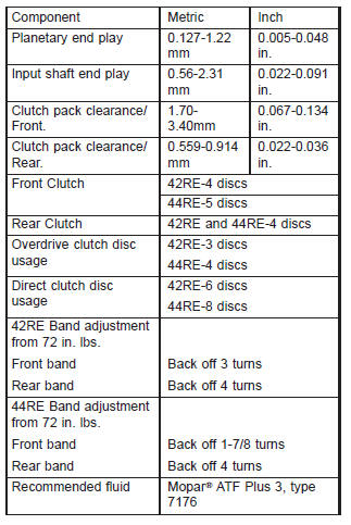
Specifications
Transmission
GEAR RATIOS
- 1ST GEAR-2.74
- 2ND GEAR-1.54
- 3RD GEAR-1.00
- 4TH GEAR-0.69
- REV.GEAR-2.21
TORQUE
DESCRIPTION TORQUE
Fitting, cooler line at trans . . . . 18 N*m (13 ft. lbs.)
Bolt, torque convertor . . . . . . . . 31 N*m (23 ft. lbs.)
Bolt/nut, crossmember . . . . . . . . 68 N*m (50 ft. lbs.)
Bolt, driveplate to crankshaft . . 75 N*m (55 ft. lbs.)
Plug, front band reaction . . . . . 17 N*m (13 ft. lbs.)
Locknut, front band adj. . . . . . . 34 N*m (25 ft. lbs.)
Switch, park/neutral . . . . . . . . . 34 N*m (25 ft. lbs.)
Bolt, fluid pan . . . . . . . . . . . . . . 17 N*m (13 ft. lbs.)
Screws, fluid filter . . . . . . . . . . . 4 N*m (35 in. lbs.)
Bolt, oil pump . . . . . . . . . . . . . . 20 N*m (15 ft. lbs.)
Bolt, overrunning clutch cam . . 17 N*m (13 ft. lbs.)
Bolt, O/D to trans. . . . . . . . . . . . 34 N*m (25 ft. lbs.)
Bolt, O/D piston retainer . . . . . . 17 N*m (13 ft. lbs.)
Plug, pressure test port . . . . . . . 14 N*m (10 ft. lbs.)
Bolt, reaction shaft support . . . . 20 N*m (15 ft. lbs.)
Locknut, rear band . . . . . . . . . . 41 N*m (30 ft. lbs.)
Bolt, valve body to case . . . . . 12 N*m (100 in. lbs.)
Screw, solenoid wiring connector . . . . . . . . . . 4 N*m (35 in. lbs.)
Screw, solenoid to transfer plate . . . . . . . . . . 4 N*m (35 in. lbs.)
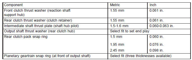
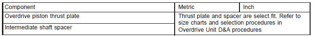
THRUST WASHER/SPACER/SNAP RING DIMENSIONS
PRESSURE TEST
| Overdrive clutch | Fourth gear only | Pressure should be 469-496 kPa (68-72 psi) with closed throttle and increase to 620-896 kPa (90-130 psi) at 1/2 to 3/4 throttle. |
| Line pressure (at accumulator) | Closed throttle | 372-414 kPa (54-60 psi). |
| Front servo | Closed throttle | No more than 21 kPa (3 psi) lower than line pressure. |
| Rear servo | 1 range R range |
No more than 21 kPa (3 psi) lower than line pressure.
1103 kPa (160 psi) at idle, builds to 1862 kPa (270 psi) at 1600 rpm. |
| Governor | D range closed throttle | Pressure should respond smoothly to changes in mph and return to 0-7 kPa (0-1.5 psi) when stopped with transmission in D, 1, 2. Pressure above 7 kPa (1.5 psi) at stand still will prevent transmission from downshifting. |
Special tools
Re transmissions
 Spring Compressor and Alignment Shaft-6227
 Gauge Bar-6311
 Extension Housing Pilot-C-3288-B
 Pressure Gauge-C-3292
 Pressure Gauge-C-3293SP
 Dial Indicator-C-3339
 Spring Compressor-C-3422-B
 Puller, Slide Hammer-C-3752
 Gauge, Throttle Setting-C-3763
 Seal Installer-C-3860-A
 Seal Remover-C-3985-B
 Installer-C-3995-A
 Universal Handle-C-4171
 Seal Installer-C-4193-A
 Dial Caliper-C-4962
 Bushing Remover/Installer Set-C-3887-J
 Nut, Bushing Remover-SP-1191, From kit C-3887-J
 Cup, Bushing Remover-SP-3633, From kit C-3887-J
 Remover, Bushing-SP-3551
 Installer, Bushing-SP-5117
 Remover, Bushing-SP-5324
 Installer, Bushing-SP-5325
 Compressor, Spring-C-3575-A
 Gauge-6312
 Adapter-C-3705
 Flusher-6906
 Installer-8114
 Remover-6957
 Installer-6951
 Retainer-6583
 Set, End-Play Tool-8266
Dodge Durango (DN) 1998-2003 Service Manual
- Lubrication and Maintenance
- Suspension
- Differential and Driveline
- Brakes
- Cooling System
- Battery
- Starting Systems
- Charging System
- Ignition System
- Instrument Panel Systems
- Audio Systems
- Horn Systems
- Speed Control System
- Turn Signal and Hazard Warning Systems
- Wiper and Washer Systems
- Lamps
- Passive Restraint Systems
- Electrically Heated Systems
- Power Distribution System
- Power Lock Systems
- Vehicle Theft/Security Systems
- Power Seat System
- Power Window Systems
- Power Mirror Systems
- Chime/Buzzer Warning Systems
- Overhead Console Systems
- Engine
- Exhaust System
- Frame and Bumpers
- Fuel System
- Steering
- Transmission and Transfer Case
- Tires and Wheels
- Body
- Heating and Air Conditioning
- Emission Control Systems
- Introduction
Categories
