Removal and installation
CAUTION: When servicing or replacing exhaust
system components, disconnect the oxygen sensor
connector(s). Allowing the exhaust to hang by the
oxygen sensor wires will damage the harness
and/or sensor. REMOVAL (1) Raise and support the vehicle.
(2) Saturate the bolts and nuts with Mopart Rust
Penetrant. Allow 5 minutes for penetration.
(3) Disconnect the oxygen sensor(s).
(4) Remove the exhaust manifold-to-exhaust pipe
nuts (Fig. 7) (Fig. 8) (Fig. 9).
(5) Remove exhaust pipe/converter to muffler
exhaust clamp.
(6) Disconnect the exhaust pipe/catalytic converter
from muffler.
(7) Remove the exhaust pipe.
1 - BOLT 2 - RETAINER 3 - EXHAUST MANIFOLD 4 - NUT 5 - EXHAUST PIPE
1 - BOLT 2 - RETAINER 3 - EXHAUST MANIFOLD 4 - NUT 5 - EXHAUST PIPE
1 - BOLT 2 - RETAINER 3 - EXHAUST MANIFOLD 4 - NUT 5 - EXHAUST PIPE INSTALLATION (1) Align and connect the exhaust pipe/catalytic
converter to the muffler. Install exhaust clamp and
tighten clamp nuts to 42 N*m (31 ft. lbs.) torque.
(2) Connect the exhaust pipe(s) to the exhaust
manifold. Tighten the nuts to 34 N*m (25 ft. lbs.)
torque.
(3) Connect oxygen sensor connector(s). (4) Lower the vehicle.
(5) Start the engine and inspect for exhaust leaks
and exhaust system contact with the body panels.
Adjust the alignment, if needed. Catalytic converter NOTE: Neither the inline catalytic converter nor the
mini catalytic converters (California emission vehicles
only) are serviceable separately from the
exhaust pipe. Refer to Exhaust Pipe for removal /
installation procedure. WARNING: IF TORCHES ARE USED WHEN WORKING
ON THE EXHAUST SYSTEM, WEAR PROTECTIVE
EYE COVERING AND DO NOT ALLOW THE
FLAME NEAR THE FUEL LINES. CAUTION: When servicing or replacing exhaust
system components, be sure to disconnect all oxygen
sensor connectors. Allowing the exhaust system
to hang by the harness will damage the wiring
and/or sensor. REMOVAL (1) Disconnect battery negative cable.
(2) Raise vehicle on hoist.
(3) Remove muffler to exhaust pipe/catalytic converter
and tailpipe clamps (Fig. 10).
(4) Remove tailpipe from hanger isolator. Heat
muffler to tailpipe with an oxygen/acetylene torch
and twist tailpipe out of muffler.
(5) Disconnect muffler from hanger isolators (Fig.
10).
(6) Heat muffler to exhaust pipe/catalytic converter
connection and twist muffler off of converter
pipe. INSTALLATION (1) Install muffler to exhaust pipe/catalytic converter
and tailpipe. Install exhaust clamps and start
nuts by hand.
(2) Connect muffler to rear muffler hanger.
(3) Connect tailpipe to rear hanger.
(4) Align muffler and tighten exhaust clamp nuts
to 42 N*m (31 ft. lbs.).
(5) Lower vehicle and connect battery negative
cable.
(6) Start engine and check for exhaust leaks.
1 - CATALYTIC CONVERTER WITH PIPE 2 - REAR MUFFLER HANGER 3 - MUFFLER 4 - CLAMP WARNING: IF TORCHES ARE USED WHEN WORKING
ON THE EXHAUST SYSTEM, WEAR PROTECTIVE
EYE COVERING AND DO NOT ALLOW THE
FLAME NEAR THE FUEL LINES. CAUTION: When servicing or replacing exhaust
system components, be sure to disconnect all oxygen
sensor connectors. Allowing the exhaust system
to hang by the harness will damage the wiring
and/or sensor. REMOVAL (1) Disconnect battery negative cable.
(2) Raise vehicle on hoist.
(3) Disconnect tailpipe from rear hanger bracket
(Fig. 11).
(4) Remove muffler to tailpipe exhaust clamp (Fig. 11).
(5) Heat connection with an oxygen/acetylene torch
and twist tailpipe out of muffler. INSTALLATION (1) Install tailpipe to muffler. Install exhaust
clamp and start nuts by hand.
(2) Connect tailpipe hanger.
(3) Align tailpipe and tighten exhaust clamp nuts
to 42 N*m (31 ft. lbs.).
(4) Lower vehicle and connect battery negative cable.
(5) Start engine and check for exhaust leaks.
1 - MUFFLER 2 - TAILPIPE HANGER INSULATOR 3 - TAILPIPE HANGER 4 - TAILPIPE 5 - CLAMP REMOVAL (1) Raise and support the vehicle.
(2) Remove the screws and nuts holding the heat
shields to the frame and floor pan (Fig. 12) (Fig. 13)
(Fig. 14). When removing muffler heat shield, the
muffler front and rear support hangers must be
removed first (Fig. 15). Be sure to disconnect both
oxygen sensor connectors.
(3) Slide the shield out around the exhaust system. INSTALLATION (1) Position the heat shields to the floor pan or the
frame and install the screws and nuts.
(2) Tighten the screws/nuts to 7 N*m (60 in. lbs.)
torque. Tighten the muffler hangers to 23 N*m (200
in. lbs.)
(3) Lower the vehicle.
1 - REAR FLOOR PAN/CONVERTER SHIELD 2 - FRONT FLOOR PAN/CONVERTER SHIELD
1 - REAR COMPARTMENT TAILPIPE SHIELD
1 - LEFT DASH HEAT SHIELD 2 - RIGHT DASH HEAT SHIELD
1 - MUFFLER HEAT SHIELD 2 - MUFFLER HANGERS Specifications Torque specifications
Exhaust pipe
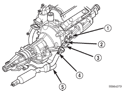 Fig. 7 Exhaust Pipe to Manifold Connection-(5.2L and 5.9L)
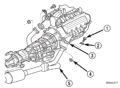 Fig. 8 Exhaust Pipe(s) to Manifold Connection- (4.7L Federal Models)
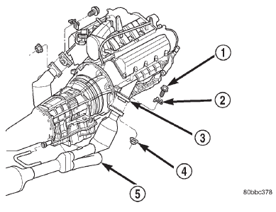 Fig. 9 Exhaust Pipe(s) to Manifold Connection- (4.7L California Models)
Muffler
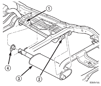 Fig. 10 Muffler Removal/Installation
Tailpipe
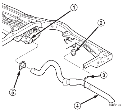 Fig. 11 Tailipipe Removal/Installation
Heat shields
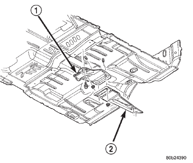 Fig. 12 Front and Rear Floor Pan/Converter Shields
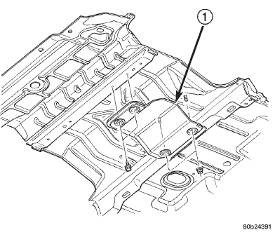 Fig. 13 Rear Compartment/Tailpipe Heat Shield
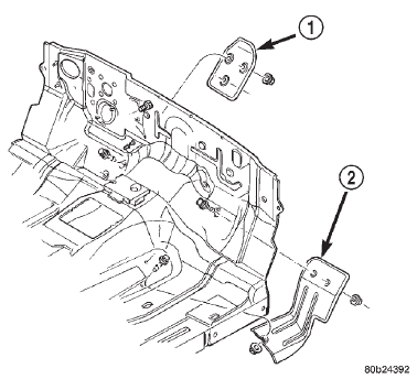 Fig. 14 Left and Right Dash Heat Shield
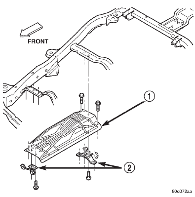 Fig. 15 Muffler Heat Shield
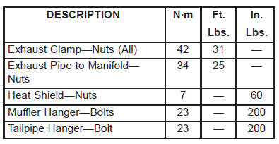
Dodge Durango (DN) 1998-2003 Service Manual
- Lubrication and Maintenance
- Suspension
- Differential and Driveline
- Brakes
- Cooling System
- Battery
- Starting Systems
- Charging System
- Ignition System
- Instrument Panel Systems
- Audio Systems
- Horn Systems
- Speed Control System
- Turn Signal and Hazard Warning Systems
- Wiper and Washer Systems
- Lamps
- Passive Restraint Systems
- Electrically Heated Systems
- Power Distribution System
- Power Lock Systems
- Vehicle Theft/Security Systems
- Power Seat System
- Power Window Systems
- Power Mirror Systems
- Chime/Buzzer Warning Systems
- Overhead Console Systems
- Engine
- Exhaust System
- Frame and Bumpers
- Fuel System
- Steering
- Transmission and Transfer Case
- Tires and Wheels
- Body
- Heating and Air Conditioning
- Emission Control Systems
- Introduction
Categories
