Removal and installation
The door ajar switch is integral to the door latch
unit. If the door ajar switch is faulty or damaged, the
entire door latch unit must be replaced. Refer to
Group 23 - Body for the door latch service procedures. Liftgate ajar switch The liftgate ajar switch is integral to the liftgate
latch unit. If the liftgate ajar switch is faulty or damaged,
the entire liftgate latch unit must be replaced.
Refer to Group 23 - Body for the liftgate latch service
procedures. (1) Disconnect and isolate the battery negative
cable.
(2) Remove the door outside latch handle mounting
hardware and linkage from the inside of the door.
Refer to Group 23 - Body for the procedures.
(3) From the outside of the door, pull the door outside
latch handle out far enough to access the door
lock cylinder switch (Fig. 2).
(4) Disengage the door lock cylinder switch from
the back of the lock cylinder.
(5) Unplug the door lock cylinder switch wire harness
connector.
(6) Disengage the retainers that secure the door
lock cylinder switch wire harness to the inner door
panel.
(7) Remove the door lock cylinder switch from the
door.
(8) Reverse the removal procedures to install. (1) Disconnect and isolate the battery negative
cable.
(2) Remove the trim panel from the liftgate inner
panel. Refer to Group 23 - Body for the procedures.
1 - DOOR OUTSIDE LATCH HANDLE 2 - DOOR 3 - DOOR LOCK CYLINDER SWITCH 4 - CONNECTOR 5 - RETAINERS (3) Reach through the access hole in the liftgate
inner panel to disengage the switch from the back of
the liftgate lock cylinder (Fig. 3).
1 - LIFTGATE INNER PANEL 2 - LIFTGATE LATCH OUTSIDE HANDLE 3 - LIFTGATE LOCK CYLINDER SWITCH 4 - WIRE HARNESS CONNECTOR (4) Unplug the liftgate lock cylinder switch wire
harness connector.
(5) Remove the liftgate lock cylinder switch from
the liftgate.
(6) Reverse the removal procedures to install. WARNING: ON VEHICLES EQUIPPED WITH AIRBAGS,
REFER TO GROUP 8M - PASSIVE
RESTRAINT SYSTEMS BEFORE ATTEMPTING ANY
STEERING WHEEL, STEERING COLUMN, OR
INSTRUMENT PANEL COMPONENT DIAGNOSIS OR
SERVICE. FAILURE TO TAKE THE PROPER PRECAUTIONS
COULD RESULT IN ACCIDENTAL AIRBAG
DEPLOYMENT AND POSSIBLE PERSONAL
INJURY. (1) Disconnect and isolate the battery negative
cable.
(2) Remove the cover from the Power Distribution
Center (PDC) (Fig. 4).
1 - CLIP 2 - BATTERY 3 - TRAY 4 - NEGATIVE CABLE 5 - POSITIVE CABLE 6 - CLIP 7 - FENDER INNER SHIELD 8 - POWER DISTRIBUTION CENTER (3) Refer to the label on the PDC for headlamp
relay identification and location.
(4) Unplug the headlamp relay from the PDC.
(5) Install the headlamp relay by aligning the
relay terminals with the cavities in the PDC and
pushing the relay firmly into place.
(6) Install the PDC cover.
(7) Connect the battery negative cable.
(8) Test the relay operation. (1) Disconnect and isolate the battery negative
cable.
(2) Remove the fuse access panel from the left end
of the instrument panel (Fig. 5).
(3) Refer to the label on the inside of the fuse
access panel for horn relay identification and location.
(4) Unplug the horn relay from the Junction Block
(JB).
(5) Install the horn relay by aligning the relay terminals
with the cavities in the JB and pushing the
relay firmly into place.
(6) Install the fuse access panel.
(7) Connect the battery negative cable.
(8) Test the relay operation.
1 - INSTRUMENT PANEL 2 - JUNCTION BLOCK 3 - FUSE ACCESS PANEL 4 - HORN RELAYDoor ajar switch
Door lock cylinder switch
Liftgate lock cylinder switch
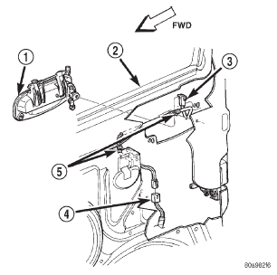 Fig. 2 Door Lock Cylinder Switch Remove/Install - Typical
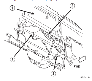 Fig. 3 Liftgate Lock Cylinder Switch Remove/Install
Headlamp relay
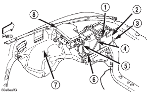 Fig. 4 Power Distribution Center
Horn relay
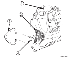 Fig. 5 Horn Relay Remove/Install
Dodge Durango (DN) 1998-2003 Service Manual
- Lubrication and Maintenance
- Suspension
- Differential and Driveline
- Brakes
- Cooling System
- Battery
- Starting Systems
- Charging System
- Ignition System
- Instrument Panel Systems
- Audio Systems
- Horn Systems
- Speed Control System
- Turn Signal and Hazard Warning Systems
- Wiper and Washer Systems
- Lamps
- Passive Restraint Systems
- Electrically Heated Systems
- Power Distribution System
- Power Lock Systems
- Vehicle Theft/Security Systems
- Power Seat System
- Power Window Systems
- Power Mirror Systems
- Chime/Buzzer Warning Systems
- Overhead Console Systems
- Engine
- Exhaust System
- Frame and Bumpers
- Fuel System
- Steering
- Transmission and Transfer Case
- Tires and Wheels
- Body
- Heating and Air Conditioning
- Emission Control Systems
- Introduction
Categories
