Removal and installation
WARNING: ON VEHICLES EQUIPPED WITH AIRBAGS,
REFER TO GROUP 8M - PASSIVE
RESTRAINT SYSTEMS BEFORE ATTEMPTING ANY
STEERING WHEEL, STEERING COLUMN, OR
INSTRUMENT PANEL COMPONENT DIAGNOSIS OR
SERVICE. FAILURE TO TAKE THE PROPER PRECAUTIONS
COULD RESULT IN ACCIDENTAL AIRBAG
DEPLOYMENT AND POSSIBLE PERSONAL
INJURY. REMOVAL (1) Disconnect and isolate the battery negative
cable.
(2) Remove the steering column opening cover
from the instrument panel. Refer to Steering Column
Opening Cover in the Removal and Installation
section of Group 8E - Instrument Panel Systems
for the procedures.
(3) Reach through the outboard side of the steering
column opening in the instrument panel to access
the relay and fuse block on the back of the junction
block (Fig. 4).
(4) Refer to Fuse/Fuse Block in the Contents of
Group 8W - Wiring Diagrams for combination flasher
identification and location.
(5) Remove the combination flasher from the relay
and fuse block. INSTALLATION (1) Refer to Fuse/Fuse Block in the Contents of
Group 8W - Wiring Diagrams for proper combination
flasher location.
(2) Position the combination flasher in the proper
receptacle in the relay and fuse block.
(3) Align the combination flasher terminals with
the terminal cavities in the relay and fuse block
receptacle.
(4) Push in firmly on the combination flasher until
the terminals are fully seated in the terminal cavities
in the relay and fuse block receptacle.
(5) Install the steering column opening cover onto
the instrument panel. Refer to Steering Column
Opening Cover in the Removal and Installation section
of Group 8E - Instrument Panel Systems for the
procedures.
(6) Reconnect the battery negative cable.
1 - ELECTRONIC COMBINATION FLASHER 2 - RELAY AND FUSE BLOCK WARNING: ON VEHICLES EQUIPPED WITH AIRBAGS,
REFER TO GROUP 8M - PASSIVE
RESTRAINT SYSTEMS BEFORE ATTEMPTING ANY
STEERING WHEEL, STEERING COLUMN, OR
INSTRUMENT PANEL COMPONENT DIAGNOSIS OR
SERVICE. FAILURE TO TAKE THE PROPER PRECAUTIONS
COULD RESULT IN ACCIDENTAL AIRBAG
DEPLOYMENT AND POSSIBLE PERSONAL
INJURY REMOVAL (1) Disconnect and isolate the battery negative
cable.
(2) If the vehicle is so equipped, unscrew the lever
from the tilt steering column adjuster mechanism
located on the left side of the column just below the
multi-function switch stalk. Turn the lever counter
clockwise to unscrew it from the column.
(3) Remove both the upper and lower shrouds from
the steering column (Fig. 5).
(4) Remove the lower fixed column shroud from
the steering column.
(5) Move the upper fixed column shroud far
enough to access the back of the multi-function
switch (Fig. 6).
(6) Remove the tamper proof mounting screws (a
Snap On tamper proof Torx bit TTXR20B2 or equivalent
is required) that secure the multi-function
switch to the steering column.
(7) Gently pull the multi-function switch away
from the steering column far enough to access and
remove the screw that secures the instrument panel wire harness connector
to the multi-function switch
connector receptacle.
(8) Disconnect the instrument panel wire harness
connector from the multi-function switch connector
receptacle.
(9) Remove the multi-function switch from the
steering column.
1 - STEERING WHEEL 2 - TILT LEVER 3 - UPPER SHROUD 4 - PANEL BRACKET 5 - SPACER 6 - TOE PLATE 7 - NUT 8 - LOWER SHROUD 9 - CLOCK SPRING 10 - NUT INSTALLATION (1) Position the multi-function switch onto the
steering column.
(2) Reconnect the instrument panel wire harness
connector to the multi-function switch connector
receptacle.
1 - WIRE HARNESS CONNECTORS 2 - SCREW 3 - WIRE HARNESS CONNECTOR 4 - MULTI-FUNCTION SWITCH 5 - WIRE HARNESS CONNECTOR 6 - CLOCKSPRING 7 - IGNITION SWITCH (3) Install and tighten the screw that secures the
instrument panel wire harness connector to the
multi-function switch connector receptacle. Tighten
the screw to 2 N*m (17 in. lbs.).
(4) Install and tighten the two screws that secure
the multi-function switch to the steering column.
Tighten the screws to 2 N*m (17 in. lbs.).
(5) Install the lower fixed column shroud onto the
steering column.
(6) Install both the upper and lower shrouds onto
the steering column.
(7) If the vehicle is so equipped, install the tilt
steering column lever onto the left side of the steering
column by screwing it into place.
(8) Reconnect the battery negative cable.Combination flasher
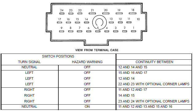 Fig. 3 Multi-Function Switch Continuity
 Fig. 4 Combination Flasher Remove/Install
Turn signal switch and hazard warning switch
 Fig. 5 Steering Column Shrouds Remove/Install - Typical
 Fig. 6 Multi-Function Switch Connector
Dodge Durango (DN) 1998-2003 Service Manual
- Lubrication and Maintenance
- Suspension
- Differential and Driveline
- Brakes
- Cooling System
- Battery
- Starting Systems
- Charging System
- Ignition System
- Instrument Panel Systems
- Audio Systems
- Horn Systems
- Speed Control System
- Turn Signal and Hazard Warning Systems
- Wiper and Washer Systems
- Lamps
- Passive Restraint Systems
- Electrically Heated Systems
- Power Distribution System
- Power Lock Systems
- Vehicle Theft/Security Systems
- Power Seat System
- Power Window Systems
- Power Mirror Systems
- Chime/Buzzer Warning Systems
- Overhead Console Systems
- Engine
- Exhaust System
- Frame and Bumpers
- Fuel System
- Steering
- Transmission and Transfer Case
- Tires and Wheels
- Body
- Heating and Air Conditioning
- Emission Control Systems
- Introduction
Categories
