Park brake release handle. Instrument panel lower reinforcement
WARNING: ON VEHICLES EQUIPPED WITH AIRBAGS,
REFER TO GROUP 8M - PASSIVE
RESTRAINT SYSTEMS BEFORE ATTEMPTING ANY
STEERING WHEEL, STEERING COLUMN, OR
INSTRUMENT PANEL COMPONENT DIAGNOSIS OR
SERVICE. FAILURE TO TAKE THE PROPER PRECAUTIONS
COULD RESULT IN ACCIDENTAL AIRBAG
DEPLOYMENT AND POSSIBLE PERSONAL
INJURY. REMOVAL (1) Disconnect and isolate the battery negative
cable.
(2) Reach under the driver side outboard end of
the instrument panel to access and unsnap the plastic
retainer clip that secures the park brake release
linkage rod to the lever on the back side of the park
brake release handle.
(3) Disengage the park brake release linkage rod
end from the lever on the back of the park brake
release handle.
(4) Using a trim stick or another suitable wide
flat-bladed tool, gently pry one of the park brake
handle hinge tabs away from its pivot pin on the
instrument panel (Fig. 10).
(5) While prying the park brake release handle
hinge tab with one hand, use the other hand to pull
the handle firmly down and away from the pivot pin.
(6) Remove the park brake release handle from the
instrument panel. INSTALLATION (1) Position the park brake release handle to the
instrument panel.
(2) Engage one of the park brake release handle
hinge tabs with one of the pivot pins on the instrument
panel.
(3) Align the second park brake release handle
hinge tab hinge over the second pivot pin on the
instrument panel.
(4) Press firmly on the park brake release handle
over the second hinge tab until it snaps over the second
pivot pin on the instrument panel.
1 - INSERT BETWEEN HINGE TAB AND PIVOT PIN 2 - TRIM STICK 3 - PARK BRAKE RELEASE HANDLE 4 - INSTRUMENT PANEL (5) Reach under the driver side outboard end of
the instrument panel to access and engage the park
brake release linkage rod end from the lever on the
back of the park brake release handle.
(6) Snap the plastic retainer clip that secures the
park brake release linkage rod to the lever on the
back side of the park brake release handle over the
linkage rod.
(7) Reconnect the battery negative cable. WARNING: ON VEHICLES EQUIPPED WITH AIRBAGS,
REFER TO GROUP 8M - PASSIVE
RESTRAINT SYSTEMS BEFORE ATTEMPTING ANY
STEERING WHEEL, STEERING COLUMN, OR
INSTRUMENT PANEL COMPONENT DIAGNOSIS OR
SERVICE. FAILURE TO TAKE THE PROPER PRECAUTIONS
COULD RESULT IN ACCIDENTAL AIRBAG
DEPLOYMENT AND POSSIBLE PERSONAL
INJURY. REMOVAL (1) Disconnect and isolate the battery negative
cable.
(2) Remove the steering column opening cover
from the instrument panel. Refer to Steering Column
Opening Cover in the Removal and Installation
section of this group for the procedures.
(3) Remove the two screws that secure the inside
hood latch release handle to the instrument panel
lower reinforcement and lower the release handle to
the floor.
(4) Depress the latch tabs that secure the 16-way
data link wire harness connector to the instrument
panel lower reinforcement, and push the connector
out of its mounting hole.
(5) Remove the four screws that secure the lower
reinforcement to the instrument panel (Fig. 11).
1 - REINFORCEMENT 2 - SCREW 3 - INSTRUMENT PANEL (6) Remove the lower reinforcement from the
instrument panel. INSTALLATION (1) Position the lower reinforcement onto the
instrument panel.
(2) Install and tighten the four screws that secure
the lower reinforcement to the instrument panel.
Tighten the screws to 2.2 N*m (20 in. lbs.).
(3) Install the 16-way data link wire harness connector
into the mounting hole on the instrument
panel lower reinforcement.
(4) Position the inside hood latch release handle to
the instrument panel lower reinforcement.
(5) Install and tighten the two screws that secure
the inside hood latch release handle to the instrument
panel lower reinforcement. Tighten the screws
to 2.8 N*m (25 in. lbs.).
(6) Install the steering column opening cover onto
the instrument panel. Refer to Steering Column
Opening Cover in the Removal and Installation section
of this group for the procedures.
(7) Reconnect the battery negative cable.Park brake release handle
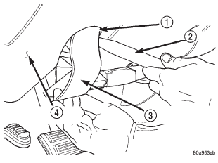 Fig. 10 Park Brake Release Handle Remove/Install
Instrument panel lower reinforcement
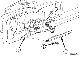 Fig. 11 Instrument Panel Lower Reinforcement Remove/Install
Dodge Durango (DN) 1998-2003 Service Manual
- Lubrication and Maintenance
- Suspension
- Differential and Driveline
- Brakes
- Cooling System
- Battery
- Starting Systems
- Charging System
- Ignition System
- Instrument Panel Systems
- Audio Systems
- Horn Systems
- Speed Control System
- Turn Signal and Hazard Warning Systems
- Wiper and Washer Systems
- Lamps
- Passive Restraint Systems
- Electrically Heated Systems
- Power Distribution System
- Power Lock Systems
- Vehicle Theft/Security Systems
- Power Seat System
- Power Window Systems
- Power Mirror Systems
- Chime/Buzzer Warning Systems
- Overhead Console Systems
- Engine
- Exhaust System
- Frame and Bumpers
- Fuel System
- Steering
- Transmission and Transfer Case
- Tires and Wheels
- Body
- Heating and Air Conditioning
- Emission Control Systems
- Introduction
Categories
