Master cylinder/power booster. Combination valve
(1) Start engine and check booster vacuum hose
connections. A hissing noise indicates vacuum leak.
Correct any vacuum leak before proceeding.
(2) Stop engine and shift transmission into Neutral.
(3) Pump brake pedal until all vacuum reserve in
booster is depleted.
(4) Press and hold brake pedal under light foot
pressure. The pedal should hold firm, if the pedal
falls away master cylinder is faulty (internal leakage).
(5) Start engine and note pedal action. It should
fall away slightly under light foot pressure then hold
firm. If no pedal action is discernible, power booster,
vacuum supply, or vacuum check valve is faulty. Proceed
to the POWER BOOSTER VACUUM TEST.
(6) If the POWER BOOSTER VACUUM TEST
passes, rebuild booster vacuum reserve as follows:
Release brake pedal. Increase engine speed to 1500
rpm, close the throttle and immediately turn off ignition
to stop engine.
(7) Wait a minimum of 90 seconds and try brake
action again. Booster should provide two or more vacuum
assisted pedal applications. If vacuum assist is
not provided, booster is faulty. POWER BOOSTER VACUUM TEST (1) Connect vacuum gauge to booster check valve
with short length of hose and T-fitting (Fig. 5).
(2) Start and run engine at curb idle speed for one
minute.
(3) Observe the vacuum supply. If vacuum supply
is not adequate, repair vacuum supply.
(4) Clamp hose shut between vacuum source and
check valve.
(5) Stop engine and observe vacuum gauge.
(6) If vacuum drops more than one inch HG (33
millibars) within 15 seconds, booster diaphragm or
check valve is faulty. POWER BOOSTER CHECK VALVE TEST (1) Disconnect vacuum hose from check valve.
1 - TEE FITTING 2 - SHORT CONNECTING HOSE 3 - CHECK VALVE 4 - CHECK VALVE HOSE 5 - CLAMP TOOL 6 - INTAKE MANIFOLD 7 - VACUUM GAUGE (2) Remove check valve and valve seal from
booster.
(3) Use a hand operated vacuum pump for test.
(4) Apply 15-20 inches vacuum at large end of
check valve (Fig. 6).
(5) Vacuum should hold steady. If gauge on pump
indicates vacuum loss, check valve is faulty and
should be replaced.
1 - BOOSTER CHECK VALVE 2 - APPLY TEST VACUUM HERE 3 - VALVE SEAL Pressure Differential Switch (1) Have helper sit in drivers seat to apply brake
pedal and observe red brake warning light.
(2) Raise vehicle on hoist.
(3) Connect bleed hose to a rear wheel cylinder
and immerse hose end in container partially filled
with brake fluid.
(4) Have helper press and hold brake pedal to floor
and observe warning light.
(a) If warning light illuminates, switch is operating
correctly.
(b) If light fails to illuminate, check circuit fuse,
bulb, and wiring. The parking brake switch can be
used to aid in identifying whether or not the brake
light bulb and fuse is functional. Repair or replace
parts as necessary and test differential pressure
switch operation again.
(5) If warning light still does not illuminate,
switch is faulty. Replace combination valve assembly,
bleed brake system and verify proper switch and
valve operation.Master cylinder/power booster
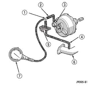 Fig. 5 Typical Booster Vacuum Test Connections
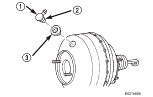 Fig. 6 Vacuum Check Valve And Seal
Combination valve
Dodge Durango (DN) 1998-2003 Service Manual
- Lubrication and Maintenance
- Suspension
- Differential and Driveline
- Brakes
- Cooling System
- Battery
- Starting Systems
- Charging System
- Ignition System
- Instrument Panel Systems
- Audio Systems
- Horn Systems
- Speed Control System
- Turn Signal and Hazard Warning Systems
- Wiper and Washer Systems
- Lamps
- Passive Restraint Systems
- Electrically Heated Systems
- Power Distribution System
- Power Lock Systems
- Vehicle Theft/Security Systems
- Power Seat System
- Power Window Systems
- Power Mirror Systems
- Chime/Buzzer Warning Systems
- Overhead Console Systems
- Engine
- Exhaust System
- Frame and Bumpers
- Fuel System
- Steering
- Transmission and Transfer Case
- Tires and Wheels
- Body
- Heating and Air Conditioning
- Emission Control Systems
- Introduction
Categories
