Gear contact pattern analysis. Side gear clearance
The ring gear and pinion teeth contact patterns
will show if the pinion depth is correct in the axle
housing. It will also show if the ring gear backlash
has been adjusted correctly. The backlash can be
adjusted within specifications to achieve desired
tooth contact patterns.
(1) Apply a thin coat of hydrated ferric oxide, or
equivalent, to the drive and coast side of the ring
gear teeth.
(2) Wrap, twist, and hold a shop towel around the
pinion yoke to increase the turning resistance of the
pinion. This will provide a more distinct contact pattern.
(3) Using a boxed end wrench on a ring gear bolt,
Rotate the differential case one complete revolution
in both directions while a load is being applied from
shop towel.
The areas on the ring gear teeth with the greatest
degree of contact against the pinion teeth will squeegee
the compound to the areas with the least amount
of contact. Note and compare patterns on the ring
gear teeth to Gear Tooth Contact Patterns chart (Fig.
81) and adjust pinion depth and gear backlash as
necessary. When measuring side gear clearance, check each
gear independently. If it necessary to replace a side
gear, replace both gears as a matched set.
(1) Install the axle shafts and C-locks and pinion
mate shaft.
(2) Measure each side gear clearance. Insert a
matched pair of feeler gauge blades between the gear
and differential housing on opposite sides of the hub
(Fig. 82).
1 - FEELER GAUGE BLADES 2 - SIDE GEAR (3) If side gear clearances is no more than 0.005
inch. Determine if the axle shaft is contacting the
pinion mate shaft. Do not remove the feeler
gauges, inspect the axle shaft with the feeler
gauge inserted behind the side gear. If the end of
the axle shaft is not contacting the pinion mate
shaft, the side gear clearance is acceptable.
(4) If clearance is more than 0.005 inch (axle shaft
not contacting mate shaft), record the side gear clearance.
Remove the thrust washer and measure its
thickness with a micrometer. Add the washer thickness
to the recorded side gear clearance. The sum of
gear clearance and washer thickness will determine
required thickness of replacement thrust washer
(Fig. 83).
In some cases, the end of the axle shaft will move
and contact the mate shaft when the feeler gauge is
inserted. The C-lock is preventing the side gear from
sliding on the axle shaft.
(5) If there is no side gear clearance, remove the
C-lock from the axle shaft. Use a micrometer to measure
the thrust washer thickness. Record the thickness
and re-install the thrust washer. Assemble the differential case without
the C-lock installed and remeasure
the side gear clearance.
(6) Compare both clearance measurements. If the
difference is less than 0.012 inch (0.305 mm), add
clearance recorded when the C-lock was installed to
thrust washer thickness measured. The sum will
determine the required thickness of the replacement
thrust washer.
(7) If clearance is 0.012 inch (0.305 mm) or
greater, both side gears must be replaced (matched
set) and the clearance measurements repeated.
(8) If clearance (above) continues to be 0.012 inch
(0.305 mm) or greater, the case must be replaced.Gear contact pattern analysis
Side gear clearance
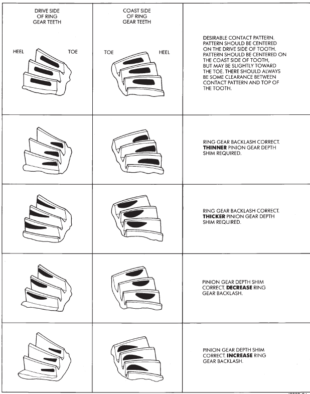 Fig. 81 Gear Tooth Contact Patterns
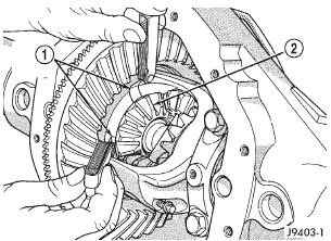 Fig. 82 Side Gear Clearance Measurement
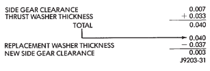 Fig. 83 Side Gear Calculations
Dodge Durango (DN) 1998-2003 Service Manual
- Lubrication and Maintenance
- Suspension
- Differential and Driveline
- Brakes
- Cooling System
- Battery
- Starting Systems
- Charging System
- Ignition System
- Instrument Panel Systems
- Audio Systems
- Horn Systems
- Speed Control System
- Turn Signal and Hazard Warning Systems
- Wiper and Washer Systems
- Lamps
- Passive Restraint Systems
- Electrically Heated Systems
- Power Distribution System
- Power Lock Systems
- Vehicle Theft/Security Systems
- Power Seat System
- Power Window Systems
- Power Mirror Systems
- Chime/Buzzer Warning Systems
- Overhead Console Systems
- Engine
- Exhaust System
- Frame and Bumpers
- Fuel System
- Steering
- Transmission and Transfer Case
- Tires and Wheels
- Body
- Heating and Air Conditioning
- Emission Control Systems
- Introduction
Categories
