Fuel gauge sending unit. Fuel injector rail-3.9/5.2/5.9L engines
The fuel gauge sending unit (fuel level sensor) and
float assembly is located on the side of fuel pump
module (Fig. 27). The fuel pump module is located
inside of fuel tank.
1 - FUEL FILTER/PRESSURE REGULATOR 2 - ELECTRICAL CONNECTOR 3 - ELECTRIC FUEL PUMP 4 - FUEL GAUGE FLOAT 5 - FUEL PUMP INLET FILTER 6 - FUEL GAUGE SENDING UNIT 7 - MODULE LOCK TABS (3) REMOVAL (1) Remove fuel tank. Refer to Fuel Tank Removal/
Installation.
(2) Remove fuel pump module. Refer to Fuel Pump
Module Removal/Installation.
(3) Unplug 4-way electrical connector (Fig. 27).
(4) Disconnect 2 sending unit wires at 4-way connector.
The locking collar of connector must be
removed before wires can be released from connector.
Note location of wires within 4-way connector.
(5) The sending unit is retained to pump module
with a small lock tab and notch (Fig. 28). Carefully
push lock tab to the side and away from notch while
sliding sending unit downward on tracks for removal.
Note wire routing while removing unit from module.
1 - FUEL GAUGE SENDING UNIT 2 - LOCK TAB 3 - NOTCH 4 - TRACKS INSTALLATION (1) Position sending unit into tracks. Note wire
routing.
(2) Push unit on tracks until lock tab snaps into
notch.
(3) Connect 2 sending unit wires into 4-way connector
and install locking collar.
(4) Connect 4-way electrical connector to module.
(5) Install fuel pump module. Refer to Fuel Pump
Module Removal/Installation.
(6) Install fuel tank. Refer to Fuel Tank Removal/
Installation. WARNING: THE FUEL SYSTEM IS UNDER A CONSTANT
PRESSURE (EVEN WITH ENGINE TURNED
OFF). BEFORE SERVICING FUEL RAIL ASSEMBLY,
FUEL SYSTEM PRESSURE MUST BE RELEASED. To release fuel pressure, refer to Fuel System Pressure
Release Procedure in this group. CAUTION: The left and right fuel rails are replaced
as an assembly. Do not attempt to separate rail
halves at connecting hose (Fig. 29). Due to the
design of this connecting hose, it does not use any
clamps. Never attempt to install a clamping device
of any kind to hose. When removing fuel rail
assembly for any reason, be careful not to bend or
kink connecting hose.
1 - FUEL RAIL CONNECTING HOSE 2 - FUEL RAIL 3 - MOUNTING BOLTS (4) REMOVAL (1) Remove negative battery cable at battery.
(2) Remove air cleaner.
(3) Perform fuel pressure release procedure.
(4) Remove throttle body from intake manifold.
Refer to Throttle Body removal in this group.
(5) If equipped with air conditioning, remove
A-shaped A/C compressor-to-intake manifold support
bracket (three bolts) (Fig. 30).
1 - AIR CONDITIONING COMPRESSOR SUPPORT BRACKET 2 - MOUNTING BOLTS (6) Disconnect electrical connectors at all 8 fuel
injectors. To remove connector refer to (Fig. 31). Push red colored slider away
from injector (1). While pushing
slider, depress tab (2) and remove connector (3)
from injector. The factory fuel injection wiring harness
is numerically tagged (INJ 1, INJ 2, etc.) for
injector position identification. If harness is not
tagged, note wiring location before removal.
(7) 3.9L (V-6) engine only: Disconnect electrical
connector at intake manifold air temperature sensor.
Do not remove sensor.
(8) Disconnect fuel tube (line) at side of fuel rail.
Refer to Quick-Connect Fittings for procedures,
(9) Remove remaining fuel rail mounting bolts.
(10) Clean dirt/debris from each fuel injector at
intake manifold.
(11) Gently rock and pull left fuel rail until fuel
injectors just start to clear intake manifold. Gently
rock and pull right fuel rail until fuel injectors just
start to clear intake manifold. Repeat this procedure
(left/right) until all fuel injectors have cleared intake
manifold.
(12) Remove fuel rail (with injectors attached)
from engine.
(13) Remove clip(s) retaining injector(s) to fuel rail
(Fig. 32) or (Fig. 33).
INSTALLATION (1) Apply a small amount of clean engine oil to
each fuel injector o-ring. This will help in fuel rail
installation.
1 - CLIP 2 - INJECTOR 3 - FUEL RAIL
1 - PLIERS 2 - INJECTOR CLIP 3 - FUEL INJECTOR 4 - FUEL RAIL (2) Install injector(s) and injector clip(s) to fuel
rail.
(3) Position fuel rail/fuel injector assembly to injector
openings on intake manifold.
(4) Guide each injector into intake manifold. Be
careful not to tear injector o-ring.
(5) Push right fuel rail down until fuel injectors
have bottomed on injector shoulder. Push left fuel rail down until fuel
injectors have bottomed on injector
shoulder.
(6) Install fuel rail mounting bolts.
(7) Connect electrical connector to intake manifold
air temperature sensor.
(8) Connect electrical connectors at all fuel injectors.
To install connector, refer to (Fig. 31). Push connector
onto injector (1) and then push and lock red
colored slider (2). Verify connector is locked to injector
by lightly tugging on connector.
(9) Install A/C support bracket (if equipped).
(10) Install throttle body to intake manifold. Refer
to Throttle Body installation in this group.
(11) Install fuel tube (line) at side of fuel rail.
Refer to Quick-Connect Fittings for procedures.
(12) Install air cleaner.
(13) Connect battery cable to battery.
(14) Start engine and check for leaks.Fuel gauge sending unit
 Fig. 27 Fuel Gauge Sending Unit Location- TYPICAL Module
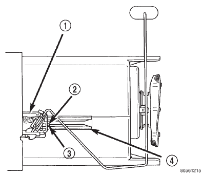 Fig. 28 Fuel Gauge Sending Unit Lock Tab/Tracks
Fuel injector rail-3.9/5.2/5.9L engines
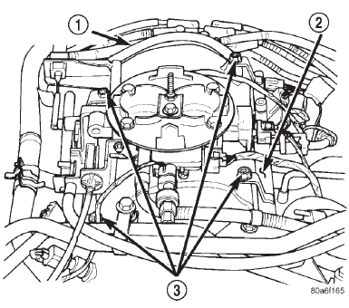 Fig. 29 Fuel Rail Assembly-3.9/5.2/5.9L Engine- Typical
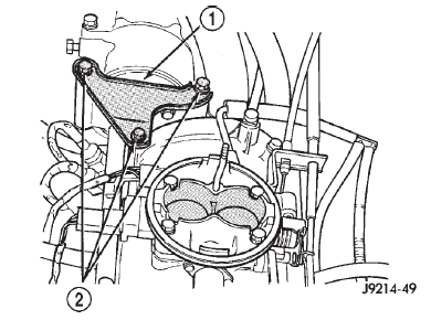 Fig. 30 A/C Compressor Support Bracket-Typical
 Fig. 31 Remove/Install Injector Connector
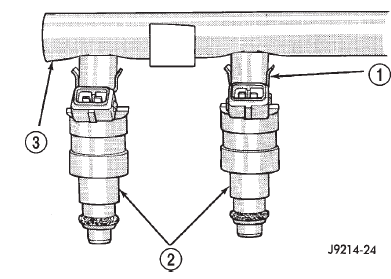 Fig. 32 Fuel Injector Mounting-Typical
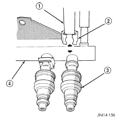 Fig. 33 Injector Retaining Clips-Typical Injector
Dodge Durango (DN) 1998-2003 Service Manual
- Lubrication and Maintenance
- Suspension
- Differential and Driveline
- Brakes
- Cooling System
- Battery
- Starting Systems
- Charging System
- Ignition System
- Instrument Panel Systems
- Audio Systems
- Horn Systems
- Speed Control System
- Turn Signal and Hazard Warning Systems
- Wiper and Washer Systems
- Lamps
- Passive Restraint Systems
- Electrically Heated Systems
- Power Distribution System
- Power Lock Systems
- Vehicle Theft/Security Systems
- Power Seat System
- Power Window Systems
- Power Mirror Systems
- Chime/Buzzer Warning Systems
- Overhead Console Systems
- Engine
- Exhaust System
- Frame and Bumpers
- Fuel System
- Steering
- Transmission and Transfer Case
- Tires and Wheels
- Body
- Heating and Air Conditioning
- Emission Control Systems
- Introduction
