Battery
DIAGNOSIS
The battery, starting system and charging system in the vehicle operate with one another, and must be tested as a complete system. In order for the engine to start and the battery to charge properly, all of the components that are used in these systems must perform within specifications. It is important that the battery, starting system and charging system be thoroughly tested and inspected any time a battery needs to be charged or replaced. The cause of abnormal discharge, overcharging or early battery failure must be diagnosed and corrected before a battery is replaced and before a vehicle is returned to service. The service information for these systems has been separated within this service manual to make it easier to locate the specific information you are seeking. However, when attempting to diagnose any of these systems, it is important that you keep their interdependency in mind.
The diagnostic procedures used for the battery, starting system and charging system include the most basic conventional diagnostic methods, to the more sophisticated On-Board Diagnostics (OBD) built into the Powertrain Control Module (PCM). Use of an induction-type milliampere ammeter, a volt/ohmmeter, a battery charger, a carbon pile rheostat (load tester) and a 12-volt test lamp may be required. All OBD-sensed systems are monitored by the PCM.
Each monitored circuit is assigned a Diagnostic Trouble Code (DTC). The PCM will store a DTC in electronic memory for any failure it detects. Refer to Charging System, On-Board Diagnostic Test in the index of this service manual for the location of the proper on-board diagnostic test procedures.
The battery must be completely charged and the top, posts and terminal clamps should be properly cleaned and inspected before any diagnostic procedures are performed. Refer to Battery in the index of this service manual for the location of the proper battery cleaning and inspection procedures. Refer to Battery Charging in the index of this service manual for the location of the proper battery charging procedures.
WARNING:
- IF THE BATTERY SHOWS SIGNS OF FREEZING, LEAKING, LOOSE POSTS, OR LOW ELECTROLYTE LEVEL, DO NOT TEST, ASSIST-BOOST, OR CHARGE. THE BATTERY MAY ARC INTERNALLY AND EXPLODE. PERSONAL INJURY AND/OR VEHICLE DAMAGE MAY RESULT.
- EXPLOSIVE HYDROGEN GAS FORMS IN AND
AROUND THE BATTERY. DO NOT SMOKE, USE
FLAME, OR CREATE SPARKS NEAR THE BATTERY.
PERSONAL INJURY AND/OR VEHICLE DAMAGE MAY RESULT.
- THE BATTERY CONTAINS SULFURIC ACID, WHICH IS POISONOUS AND CAUSTIC. AVOID CONTACT WITH THE SKIN, EYES, OR CLOTHING. IN THE EVENT OF CONTACT, FLUSH WITH WATER AND CALL A PHYSICIAN IMMEDIATELY. KEEP OUT OF THE REACH OF CHILDREN.
- IF THE BATTERY IS EQUIPPED WITH REMOVABLE CELL CAPS, BE CERTAIN THAT EACH OF THE CELL CAPS IS IN PLACE AND TIGHT BEFORE THE BATTERY IS RETURNED TO SERVICE. PERSONAL INJURY AND/OR VEHICLE DAMAGE MAY RESULT FROM LOOSE OR MISSING CELL CAPS.
The condition of a battery is determined by two criteria:
1. State-Of-Charge
This can be determined by checking the specific gravity of the battery electrolyte (built-in test indicator or hydrometer test), or by checking the battery voltage (open-circuit voltage test).
2. Cranking Capacity
This can be determined by performing a battery load test, which measures the ability of the battery to supply high-amperage current.
First, determine the battery state-of-charge. This can be done in one of three ways. If the battery has a built-in test indicator, view the test indicator to determine the state-of-charge. If the battery has no test indicator but does have removable cell caps, perform the hydrometer test to determine the state-ofcharge.
If the battery cell caps are not removable or a hydrometer is not available, perform the open-circuit voltage test to determine the state-of-charge.
The battery must be charged before proceeding with a load test if:
- The battery built-in test indicator has a black or dark color visible.
- The temperature corrected specific gravity of the battery electrolyte is less than 1.235.
- The battery open-circuit voltage is less than 12.4 volts.
A battery that will not accept a charge is faulty, and must be replaced. Further testing is not required. A fully-charged battery must be load tested to determine its cranking capacity. A battery that is fully-charged but does not pass the load test is faulty, and must be replaced.
NOTE: Completely discharged batteries may take several hours to accept a charge. Refer to Battery Charging in the index of this service manual for the location of the proper battery charging procedures.
A battery is fully-charged when:
- All battery cells are gassing freely during charging.
- A green color is visible in the sight glass of the battery built-in test indicator.
- Three corrected specific gravity tests, taken at one-hour intervals, indicate no increase in the specific gravity of the battery electrolyte.
- Open-circuit voltage of the battery is 12.4 volts or greater.
|
Battery Diagnosis |
||
| Condition | Possible Causes | Correction |
| The battery seems weak or dead when attempting to start the engine. | 1. The battery has an
incorrect size or rating for
this vehicle.
2. The battery is physically damaged. 3. The battery terminal connections are loose or corroded. 4. The battery is discharged. 5. The electrical system ignition-off draw is excessive. 6. The battery is faulty. 7. The starting system is faulty. 8. The charging system is faulty. |
1. Refer to Battery in the index of this service
manual for the location of the proper battery
specifications. Replace an incorrect battery, as
required.
2. Inspect the battery for loose terminal posts or a cracked and leaking case. Replace the damaged battery, as required. 3. Refer to Voltage Drop Test in this section for the proper test procedures. Clean and tighten the battery terminal connections, as required. 4. Determine the battery state-of-charge. Refer to Built-In Test Indicator, Hydrometer Test, or Open-Circuit Voltage Test in this section for the proper test procedures. Charge the faulty battery, as required. 5. Refer to Ignition-Off Draw Test in this section for the proper test procedures. Repair the faulty electrical system, as required. 6. Determine the battery cranking capacity. Refer to Load Test in this section for the proper test procedures. Replace the faulty battery, as required. 7. Determine if the starting system is performing to specifications. Refer to Starting System in the index of this service manual for the location of the proper starting system diagnosis and testing procedures. Repair the faulty starting system, as required. 8. Determine if the charging system is performing to specifications. Refer to Charging System in the index of this service manual for the location of the proper charging system diagnosis and testing procedures. Repair the faulty charging system, as required. |
| The battery state-of-charge cannot be maintained. | 1. The battery has an
incorrect size or rating for
this vehicle.
2. The battery terminal connections are loose or corroded. 3. The generator drive belt is slipping. 4. The electrical system ignition-off draw is excessive. 5. The battery is faulty. 6. The starting system is faulty. 7. The charging system is faulty. 8. Electrical loads exceed the output of the charging system. 9. Slow driving or prolonged idling with high-amperage draw systems in use. |
1. Refer to Battery in the index of this service
manual for the location of the proper battery
specifications. Replace an incorrect battery, as
required.
2. Refer to Voltage Drop Test in this section for the proper test procedures. Clean and tighten the battery terminal connections, as required. 3. Refer to Accessory Drive Belt Diagnosis in the index of this service manual for the location of the proper accessory drive belt diagnosis and testing procedures. Replace or adjust the faulty generator drive belt, as required. 4. Refer to Ignition-Off Draw Test in this section for the proper test procedures. Repair the faulty electrical system, as required. 5. Determine the battery cranking capacity. Refer to Load Test in this section for the proper test procedures. Replace the faulty battery, as required. 6. Determine if the starting system is performing to specifications. Refer to Starting System in the index of this service manual for the location of the proper starting system diagnosis and testing procedures. Repair the faulty starting system, as required. 7. Determine if the charging system is performing to specifications. Refer to Charging System in the index of this service manual for the location of the proper charging system diagnosis and testing procedures. Repair the faulty charging system, as required. 8. Inspect the vehicle for aftermarket electrical equipment which might cause excessive electrical loads. 9. Advise the vehicle operator, as required. |
| The battery will not accept a charge. | 1. The battery is faulty. | 1. Refer to Battery Charging in the index of this service manual for the location of the proper battery charging procedures. Charge or replace the faulty battery, as required. |
ABNORMAL BATTERY DISCHARGING
Any of the following conditions can result in abnormal battery discharging: 1. Corroded or loose battery posts and terminal clamps.
2. A loose or worn generator drive belt.
3. Electrical loads that exceed the output of the charging system. This can be due to equipment installed after manufacture, or repeated short trip use.
4. Slow driving speeds (heavy traffic conditions) or prolonged idling, with high-amperage draw systems in use.
5. A faulty circuit or component causing excessive ignition-off draw.
6. A faulty or incorrect charging system component.
Refer to Charging System in the index of this service manual for the location of the proper charging system diagnosis and testing procedures.
7. A faulty or incorrect starting system component.
Refer to Starting System in the index of this service manual for the location of the proper starting system diagnosis and testing procedures.
8. A faulty or incorrect battery.
TESTING
BUILT-IN TEST INDICATOR
A test indicator (hydrometer) built into the top of the battery case provides visual information for battery testing (Fig. 5). Like a hydrometer, the built-in test indicator measures the specific gravity of the battery electrolyte. The test indicator reveals the battery state-of-charge; however, it will not reveal the cranking capacity of the battery. A load test must be performed to determine the battery cranking capacity.
Refer to Load Test in this section for the proper battery load testing procedures.
 Fig. 5 Built-In Test Indicator
1 - SIGHT GLASS
2 - BATTERY TOP
3 - GREEN BALL
4 - PLASTIC ROD
WARNING:
- IF THE BATTERY SHOWS SIGNS OF FREEZING, LEAKING, LOOSE POSTS, OR LOW ELECTROLYTE LEVEL, DO NOT TEST, ASSIST-BOOST, OR CHARGE. THE BATTERY MAY ARC INTERNALLY AND EXPLODE. PERSONAL INJURY AND/OR VEHICLE DAMAGE MAY RESULT.
- EXPLOSIVE HYDROGEN GAS FORMS IN AND
AROUND THE BATTERY. DO NOT SMOKE, USE
FLAME, OR CREATE SPARKS NEAR THE BATTERY.
PERSONAL INJURY AND/OR VEHICLE DAMAGE MAY RESULT.
- THE BATTERY CONTAINS SULFURIC ACID, WHICH IS POISONOUS AND CAUSTIC. AVOID CONTACT WITH THE SKIN, EYES, OR CLOTHING. IN THE EVENT OF CONTACT, FLUSH WITH WATER AND CALL A PHYSICIAN IMMEDIATELY. KEEP OUT OF THE REACH OF CHILDREN.
- IF THE BATTERY IS EQUIPPED WITH REMOVABLE CELL CAPS, BE CERTAIN THAT EACH OF THE CELL CAPS IS IN PLACE AND TIGHT BEFORE THE BATTERY IS RETURNED TO SERVICE. PERSONAL INJURY AND/OR VEHICLE DAMAGE MAY RESULT FROM LOOSE OR MISSING CELL CAPS.
Before testing, visually inspect the battery for any damage (a cracked case or cover, loose posts, etc.) that would cause the battery to be faulty. In order to obtain correct indications from the built-in test indicator, it is important that the battery be level and have a clean sight glass. Additional light may be required to view the indicator. Do not use open flame as a source of additional light.
To read the built-in test indicator, look into the sight glass and note the color of the indicator (Fig. 6).
The battery condition that each color indicates is described in the following list:
- Green
Indicates 75% to 100% battery state-of-charge. The battery is adequately charged for further testing or return to service. If the starter will not crank for a minimum of fifteen seconds with a fully-charged battery, the battery must be load tested. Refer to Load Test in this section for the proper battery load testing procedures.
- Black or Dark
Indicates 0% to 75% battery state-of-charge. The battery is inadequately charged and must be charged until a green indication is visible in the sight glass (12.4 volts or more), before the battery is tested further or returned to service. Refer to Battery Charging in the index of this service manual for the location of the proper battery charging procedures.
Also refer to Abnormal Battery Discharging in this section for the possible causes of the discharged battery condition.
- Clear or Bright
Indicates a low battery electrolyte level. The electrolyte level in the battery is below the test indicator. A maintenance-free battery with non-removable cell caps must be replaced if the electrolyte level is low.
Water must be added to a low-maintenance battery with removable cell caps before it is charged. Refer to Battery Charging in the index of this service manual for the location of the proper battery charging procedures. A low electrolyte level may be caused by an overcharging condition. Refer to Charging System in the index of this service manual for the location of the proper charging system diagnosis and testing procedures.
HYDROMETER TEST
The hydrometer test reveals the battery state-ofcharge by measuring the specific gravity of the electrolyte.
This test cannot be performed on maintenance-free batteries with non-removable cell caps. If the battery has non-removable cell caps, refer to Built-In Test Indicator or Open-Circuit Voltage Test in this section for the proper procedures for performing these alternate tests of the battery state-of-charge.
 Fig. 6 Built-In Test Indicator Sight Glass
Specific gravity is a comparison of the density of the battery electrolyte to the density of pure water.
Pure water has a specific gravity of 1.000, and sulfuric acid has a specific gravity of 1.835. Sulfuric acid makes up approximately 35% of the battery electrolyte by weight, or 24% by volume. In a fully-charged battery the electrolyte will have a temperature-corrected specific gravity of 1.260 to 1.290. However, a specific gravity of 1.235 or above is satisfactory for battery load testing and/or return to service.
WARNING:
- IF THE BATTERY SHOWS SIGNS OF FREEZING, LEAKING, LOOSE POSTS, OR LOW ELECTROLYTE LEVEL, DO NOT TEST, ASSIST-BOOST, OR CHARGE. THE BATTERY MAY ARC INTERNALLY AND EXPLODE. PERSONAL INJURY AND/OR VEHICLE DAMAGE MAY RESULT.
- EXPLOSIVE HYDROGEN GAS FORMS IN AND
AROUND THE BATTERY. DO NOT SMOKE, USE
FLAME, OR CREATE SPARKS NEAR THE BATTERY.
PERSONAL INJURY AND/OR VEHICLE DAMAGE MAY RESULT.
- THE BATTERY CONTAINS SULFURIC ACID, WHICH IS POISONOUS AND CAUSTIC. AVOID CONTACT WITH THE SKIN, EYES, OR CLOTHING. IN THE EVENT OF CONTACT, FLUSH WITH WATER AND CALL A PHYSICIAN IMMEDIATELY. KEEP OUT OF THE REACH OF CHILDREN
- IF THE BATTERY IS EQUIPPED WITH REMOVABLE CELL CAPS, BE CERTAIN THAT EACH OF THE CELL CAPS IS IN PLACE AND TIGHT BEFORE THE BATTERY IS RETURNED TO SERVICE. PERSONAL INJURY AND/OR VEHICLE DAMAGE MAY RESULT FROM LOOSE OR MISSING CELL CAPS.
Before testing, visually inspect the battery for any damage (a cracked case or cover, loose posts, etc.) that would cause the battery to be faulty. Then remove the battery cell caps and check the electrolyte level. Add distilled water if the electrolyte level is below the top of the battery plates.
See the instructions provided by the manufacturer of the hydrometer for recommendations on the correct use of the hydrometer that you are using.
Remove only enough electrolyte from the battery cell so that the float is off the bottom of the hydrometer barrel with pressure on the bulb released. To read the hydrometer correctly, hold it with the top surface of the electrolyte at eye level (Fig. 7).
CAUTION: Exercise care when inserting the tip of the hydrometer into a battery cell to avoid damaging the plate separators. Damaged plate separators can cause early battery failure.
 Fig. 7 Hydrometer - Typical
1 - BULB
2 - SURFACE COHESION
3 - SPECIFIC GRAVITY READING
4 - TEMPERATURE READING
5 - HYDROMETER BARREL
6 - FLOAT
Hydrometer floats are generally calibrated to indicate the specific gravity correctly only at 26.7 C (80 F). When testing the specific gravity at any other temperature, a correction factor is required. The correction factor is approximately a specific gravity value of 0.004, which may also be identified as four points of specific gravity. For each 5.5 C above 26.7 C (10 F above 80 F), add four points. For each 5.5 C below 26.7 C (10 F below 80 F), subtract four points. Always correct the specific gravity for temperature variation.
EXAMPLE: A battery is tested at -12.2 C (10 F) and has a specific gravity of 1.240. Determine the actual specific gravity as follows:
(1) Determine the number of degrees above or below 26.7 C (80 F): 26.6 C - -12.2 C = 38.8 C (80 F - 10 F = 70 F) (2) Divide the result from Step 1 by 5.5 C (10 F): 38.8 C 4 5.5 C = 7 (70 F 4 10 F = 7) (3) Multiply the result from Step 2 by the temperature correction factor (0.004): 7 X 0.004 = 0.028 (4) The temperature at testing was below 26.7 C (80 F); therefore, the temperature correction factor is subtracted: 1.240 - 0.028 = 1.212 (5) The corrected specific gravity of the battery cell in this example is 1.212.
Test the specific gravity of the electrolyte in each battery cell. If the specific gravity of all cells is above 1.235, but the variation between cells is more than fifty points (0.050), the battery should be replaced. If the specific gravity of one or more cells is less than 1.235, charge the battery at a rate of approximately five amperes. Continue charging the battery until three consecutive specific gravity tests, taken at onehour intervals, are constant. If the cell specific gravity variation is more than fifty points (0.050) at the end of the charge period, replace the battery.
When the specific gravity of all cells is above 1.235, and the cell variation is less than fifty points (0.050), the battery may be load tested to determine its cranking capacity. Refer to Load Test in this section for the proper battery load testing procedures.
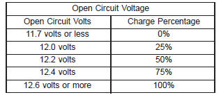
OPEN-CIRCUIT VOLTAGE TEST
A battery open-circuit voltage (no load) test will show the state-of-charge of a battery. This test can be used in place of the hydrometer test when a hydrometer is not available, or for maintenance-free batteries with non-removable cell caps.
WARNING:
- IF THE BATTERY SHOWS SIGNS OF FREEZING, LEAKING, LOOSE POSTS, OR LOW ELECTROLYTE LEVEL, DO NOT TEST, ASSIST-BOOST, OR CHARGE. THE BATTERY MAY ARC INTERNALLY AND EXPLODE. PERSONAL INJURY AND/OR VEHICLE DAMAGE MAY RESULT.
- EXPLOSIVE HYDROGEN GAS FORMS IN AND
AROUND THE BATTERY. DO NOT SMOKE, USE
FLAME, OR CREATE SPARKS NEAR THE BATTERY.
PERSONAL INJURY AND/OR VEHICLE DAMAGE MAY RESULT.
- THE BATTERY CONTAINS SULFURIC ACID, WHICH IS POISONOUS AND CAUSTIC. AVOID CONTACT WITH THE SKIN, EYES, OR CLOTHING. IN THE EVENT OF CONTACT, FLUSH WITH WATER AND CALL A PHYSICIAN IMMEDIATELY. KEEP OUT OF THE REACH OF CHILDREN.
- IF THE BATTERY IS EQUIPPED WITH REMOVABLE CELL CAPS, BE CERTAIN THAT EACH OF THE CELL CAPS IS IN PLACE AND TIGHT BEFORE THE BATTERY IS RETURNED TO SERVICE. PERSONAL INJURY AND/OR VEHICLE DAMAGE MAY RESULT FROM LOOSE OR MISSING CELL CAPS.
Before proceeding with this test, completely charge the battery. Refer to Battery Charging in the index of this service manual for the location of the proper battery charging procedures.
(1) Before measuring the open-circuit voltage, the surface charge must be removed from the battery.
Turn on the headlamps for fifteen seconds, then allow up to five minutes for the battery voltage to stabilize.
(2) Disconnect and isolate both battery cables, negative cable first.
(3) Using a voltmeter connected to the battery posts (see the instructions provided by the manufacturer of the voltmeter), measure the open-circuit voltage (Fig. 8).
 Fig. 8 Testing Open-Circuit Voltage - Typical
See the Open-Circuit Voltage chart. This voltage
reading will indicate the battery state-of-charge, but
will not reveal its cranking capacity. If a battery has
an open-circuit voltage reading of 12.4 volts or
greater, it may be load tested to reveal its cranking
capacity. Refer to Load Test in this section for the
proper battery load testing procedures.
LOAD TEST
A battery load test will verify the battery cranking capacity. This test is based on the Cold Cranking Amperage (CCA) rating of the battery. See the label affixed to the battery case, or refer to Battery in the index of this service manual for the location of the proper factory-installed battery specifications to determine the battery CCA rating.
WARNING:
- IF THE BATTERY SHOWS SIGNS OF FREEZING, LEAKING, LOOSE POSTS, OR LOW ELECTROLYTE LEVEL, DO NOT TEST, ASSIST-BOOST, OR CHARGE. THE BATTERY MAY ARC INTERNALLY AND EXPLODE. PERSONAL INJURY AND/OR VEHICLE DAMAGE MAY RESULT.
- EXPLOSIVE HYDROGEN GAS FORMS IN AND
AROUND THE BATTERY. DO NOT SMOKE, USE
FLAME, OR CREATE SPARKS NEAR THE BATTERY.
PERSONAL INJURY AND/OR VEHICLE DAMAGE MAY RESULT.
- THE BATTERY CONTAINS SULFURIC ACID, WHICH IS POISONOUS AND CAUSTIC. AVOID CONTACT WITH THE SKIN, EYES, OR CLOTHING. IN THE EVENT OF CONTACT, FLUSH WITH WATER AND CALL A PHYSICIAN IMMEDIATELY. KEEP OUT OF THE REACH OF CHILDREN.
- IF THE BATTERY IS EQUIPPED WITH REMOVABLE CELL CAPS, BE CERTAIN THAT EACH OF THE CELL CAPS IS IN PLACE AND TIGHT BEFORE THE BATTERY IS RETURNED TO SERVICE. PERSONAL INJURY AND/OR VEHICLE DAMAGE MAY RESULT FROM LOOSE OR MISSING CELL CAPS.
Before proceeding with this test, completely charge the battery. Refer to Battery Charging in the index of this service manual for the location of the proper battery charging procedures.
(1) Disconnect and isolate both battery cables, negative cable first. The battery top and posts should be clean.
(2) Connect a suitable volt-ammeter-load tester (Fig. 9) to the battery posts (Fig. 10). See the instructions provided by the manufacturer of the tester you are using. Check the open-circuit voltage (no load) of the battery. Refer to Open-Circuit Voltage Test in this section for the proper battery open-circuit voltage testing procedures. The battery open-circuit voltage must be 12.4 volts or greater.
(3) Rotate the load control knob (carbon pile rheostat) to apply a 300 ampere load to the battery for fifteen seconds, then return the control knob to the Off position (Fig. 11). This will remove the surface charge from the battery.
(4) Allow the battery to stabilize to open-circuit voltage. It may take up to five minutes for the battery voltage to stabilize.
(5) Rotate the load control knob to maintain a load equal to 50% of the CCA rating of the battery (Fig.
12). After fifteen seconds, record the loaded voltage reading, then return the load control knob to the Off position.
 Fig. 9 Volt-Ammeter-Load Tester - Typical
 Fig. 10 Volt-Ammeter-Load Tester Connections - Typical
1 - INDUCTION AMMETER CLAMP
2 - NEGATIVE CLAMP
3 - POSITIVE CLAMP
 Fig. 11 Remove Surface Charge from Battery - Typical
 Fig. 12 Load 50% CCA Rating - Note Voltage - Typical
(6) The voltage drop will vary with the battery
temperature at the time of the load test. The battery
temperature can be estimated by using the ambient
temperature during the past several hours. If the
battery has been charged, boosted, or loaded a few
minutes prior to the test, the battery will be somewhat
warmer. See the Load Test Temperature chart
for the proper loaded voltage reading.
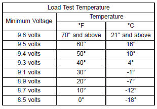
(7) If the voltmeter reading falls below 9.6 volts, at a minimum battery temperature of 21 C (70 F), the battery is faulty and must be replaced.
IGNITION-OFF DRAW TEST
The term Ignition-Off Draw (IOD) identifies a normal condition where power is being drained from the battery with the ignition switch in the Off position. A normal vehicle electrical system will draw from five to twenty-five milliamperes (0.005 to 0.025 ampere) with the ignition switch in the Off position, and all non-ignition controlled circuits in proper working order. The twenty-five milliamperes are needed to enable the memory functions for the Powertrain Control Module (PCM), digital clock, electronically tuned radio, and other electronic modules which may vary with the vehicle equipment.
A vehicle that has not been operated for approximately twenty days, may discharge the battery to an inadequate level. When a vehicle will not be used for twenty days or more (stored), remove the IOD fuse from the Junction Block (JB). This will reduce battery discharging.
Excessive IOD can be caused by:
- Electrical items left on.
- Faulty or improperly adjusted switches.
- Faulty or shorted electronic modules and components.
- An internally shorted generator.
- Intermittent shorts in the wiring.
If the IOD is over twenty-five milliamperes, the problem must be found and corrected before replacing a battery. In most cases, the battery can be charged and returned to service after the excessive IOD condition has been corrected.
(1) Verify that all electrical accessories are off.
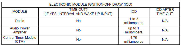
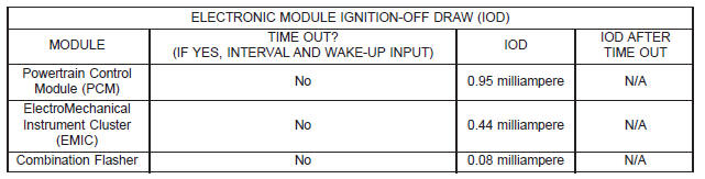
Turn off all lamps, remove the ignition key, and close all doors. If the vehicle is equipped with an illuminated entry system or an electronically tuned radio, allow the electronic timer function of these systems to automatically shut off (time out). This may take up to three minutes. See the Electronic Module Ignition- Off Draw table for more information.
(2) Determine that the under-hood lamp is operating properly, then disconnect the lamp wire harness connector or remove the lamp bulb.
(3) Disconnect the battery negative cable.
(4) Set an electronic digital multi-meter to its highest amperage scale. Connect the multi-meter between the disconnected battery negative cable terminal clamp and the battery negative terminal post.
Make sure that the doors remain closed so that the illuminated entry system is not activated. The multimeter amperage reading may remain high for up to three minutes, or may not give any reading at all while set in the highest amperage scale, depending upon the electrical equipment in the vehicle. The multi-meter leads must be securely clamped to the battery negative cable terminal clamp and the battery negative terminal post. If continuity between the battery negative terminal post and the negative cable terminal clamp is lost during any part of the IOD test, the electronic timer function will be activated and all of the tests will have to be repeated.
(5) After about three minutes, the high-amperage IOD reading on the multi-meter should become very low or nonexistent, depending upon the electrical equipment in the vehicle. If the amperage reading remains high, remove and replace each fuse or circuit breaker in the Power Distribution Center (PDC), the Junction Block (JB) and the relay and fuse block one at a time (refer to Power Distribution Center, Junction Block and Fuse/Fuse Block in the index of this service manual for the location of complete PDC, JB and relay and fuse block fuse and circuit breaker identification contained in the wiring diagrams) until the amperage reading becomes very low, or nonexistent. This will isolate each circuit and identify the circuit that is the source of the high-amperage IOD. If the amperage reading remains high after removing and replacing each fuse and circuit breaker, disconnect the wire harness from the generator.
If the amperage reading now becomes very low or nonexistent, refer to Charging System in the index of this service manual for the location of the proper charging system diagnosis and testing procedures.
After the high-amperage IOD has been corrected, switch the multi-meter to progressively lower amperage scales and, if necessary, repeat the fuse and circuit breaker remove-and-replace process to identify and correct all sources of excessive IOD. It is now safe to select the lowest milliampere scale of the multi-meter to check the low-amperage IOD.
CAUTION: Do not open any doors, or turn on any electrical accessories with the lowest milliampere scale selected, or the multi-meter may be damaged.
6) Observe the multi-meter reading. The low-amperage IOD should not exceed twenty-five milliamperes (0.025 ampere). If the current draw exceeds twenty-five milliamperes, isolate each circuit using the fuse and circuit breaker remove-and-replace process in Step 5. The multi-meter reading will drop to within the acceptable limit when the source of the excessive current draw is disconnected. Repair this circuit as required; whether a wiring short, incorrect switch adjustment, or a component failure is at fault.
Dodge Durango (DN) 1998-2003 Service Manual
- Lubrication and Maintenance
- Suspension
- Differential and Driveline
- Brakes
- Cooling System
- Battery
- Starting Systems
- Charging System
- Ignition System
- Instrument Panel Systems
- Audio Systems
- Horn Systems
- Speed Control System
- Turn Signal and Hazard Warning Systems
- Wiper and Washer Systems
- Lamps
- Passive Restraint Systems
- Electrically Heated Systems
- Power Distribution System
- Power Lock Systems
- Vehicle Theft/Security Systems
- Power Seat System
- Power Window Systems
- Power Mirror Systems
- Chime/Buzzer Warning Systems
- Overhead Console Systems
- Engine
- Exhaust System
- Frame and Bumpers
- Fuel System
- Steering
- Transmission and Transfer Case
- Tires and Wheels
- Body
- Heating and Air Conditioning
- Emission Control Systems
- Introduction
Categories
